
Operating instructions

08/06 57
5.1.9 Filter time constant
The time constant of the filter for the reference analog value can be set via the pa-
rameter
Filter time constant 561.
T
he time constant states the time for which the input si
g
nal is avera
g
ed by means of a
low pass filter, e.g. in order to eliminate fault effects.
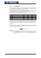
The setting range is a range of values between 0 ms and 5000 ms in 15 steps.
Operation mode Function
0 -Time constant 0 ms
Filter deactivated – analog reference value is for-
warded unfiltered
2 -Time constant 2 ms
4 -Time constant 4 ms
8 -Time constant 8 ms
16 -Time constant 16 ms
32 -Time constant 32 ms
64 -Time constant 64 ms
128 -Time constant 128 ms
256 -Time constant 256 ms
512 -Time constant 512 ms
1000 -Time constant 1000 ms
2000 -Time constant 2000 ms
3000 -Time constant 3000 ms
4000 -Time constant 4000 ms
5000 -Time constant 5000 ms
Filter activated – averaging of the input signal via
the set value of the filter time constants
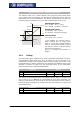
5.2 Resolver input EM-RES
The resolver input is used for evaluating the position information from the resolver.
The frequency of the field signal for the resolver can be selected via parameter Opera-
tion Mode
380.
Operation mode Function
5- frequency 5 kHz
10- frequency 10 kHz
20- frequency 20 kHz
Frequency of the reference signal for the resolver
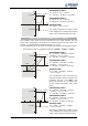
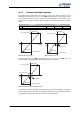
If the no. of resolver pole pairs > 1, the measured electric an
g
le runs throu
g
h the
range of 0°...360° several times during one mechanical revolution.
For the detection of the position an
g
le of the rotor at a synchronous motor, the ratio
of the no. of motor pole pairs to the no. of resolver pole pairs must be an integer.
The no. of pole pairs of the resolver can be adjusted via parameter
No. of Pole Pairs
381.
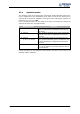
Parameter Function
No. Description Min. Max. Fact. sett.
381 No. of pole pairs 1 24 1
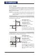
assignment of the socket:
Resolver field signal EM-RES (X410A.1): REF+
Resolver field signal EM-RES (X410A.2): REF-
Resolver input EM-RES (X410A.3): SIN-
Resolver input EM-RES (X410A.4): SIN+
Resolver input EM-RES (X410A.5): COS-
Resolver input EM-RES (X410A.6): COS+