
Operating instructions

58 08/06
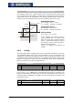
5.2.1 Offset
In order to enable the start of a synchronous machine, the absolute position of the
rotor must be known. This information is required in order to actuate the stator wind-
ings in the right order depending on the position of the rotor. The position of the rotary
field in the synchronous machine must be controlled in order to obtain a continuous
movement of the rotor. During first commissioning, the position of the rotor windin
g
o
f
the resolver is adjusted to the rotor displacement angle of the synchronous motor b
y
ad
j
ustin
g
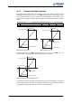
the offset. For operatin
g
a synchronous machine with resolver, the offse
t
must be adjusted in order to obtain perfectly true running and a maximum torque.
The correct
Offset 382 is adjusted when the flux-forming voltage 235 reaches the
value 0 (approximately) while the motor is turning.
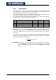
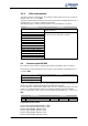
Parameter Function
No. Description Min. Max. Fact. sett.
382 Offset -360.0° 360.0° 0.0°
The offset can be determined and adjusted as follows:
• Durin
g
first commissionin
g
"SEtUP" will be displayed in the control unit. Press ESC
to stop this operation. The guided commissioning („SETUP“) is performed after ad-
justing the offset.
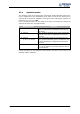
• Open the parameter menu "PARA" and enter the machine data indicated on the
type plate or the data sheet of the motor.
• Set parameter Operation Mode 380 to the frequency value of the field si
g
nal fo
r
the resolver.
• Adjust parameter No. of Pole Pairs 381 to the number of pole pairs of the resolver.
Before adjusting the offset, take the following safety precautions:
• Disable the frequency inverter via digital input S1IND (controller release).
• If possible, uncouple the motor from the load so that the motor shaft turns freely. I
f
installed, release the mechanical brake.
If uncoupling is not possible, make sure that the motor is loaded as little as possi-
ble.
Warning! In certain circumstances, the motor speed may reach hi
g
h values. If the
motor is not uncoupled from the load, personal and material dama
g
e
may result. To avoid such dama
g
e, make the followin
g
settin
g
s in any
case.
• Set the max. permissible output frequency of the frequency inverter to a low fre-
quency value via parameter
Switch-Off Limit 417. Select the frequency value such
that uncontrolled acceleration of the motor ("overspeedin
g
") is detected at an earl
y
stage. This limitation is necessary in order to avoid personal and material damage.
• Set parameter Current Limit 728 of the speed controller to a low current value
(e.
g
. 10% of the rated motor current). In this way it is made sure that there are no
excessive currents of the offset is set incorrectly.