
Operating instructions

08/06 59
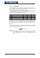
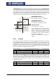
• Turn motor shaft manually. Check the sense of rotation of the resolver via the ac-
tual value of parameter
Frequency Speed Sensor 2 219. In the case of a clock-wise
rotation of the motor shaft, positive values are displayed for the actual frequency
value. If the displayed sense of rotation does not correspond to the actual sense o
f
rotation, change the connections SIN+ and SIN- at socket X410A of the frequency
inverter.
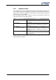
The Offset 382 must be between 0° and 360°, divided by the number of motor pole
pairs. If the number of resolver pole pairs is higher than 1, the possible range is be-
tween 0° and the max. offset.
number of motor pole pairs / number of resolver pole pairs
360
Offset Max.
°
=
If the adjusted value is changed by the max. offset, this does not affect the flux-
f
orming voltage 235.
• Adjust a low reference speed value (approx. 10% lower than the Switch-off Limi
t
Frequency
417), and enable the frequency inverter via digital input S1IND (control-
ler release) and S2IND (start clock-wise operation) in order to accelerate the motor.
• If an overcurrent is detected or a fault messa
g
e is issued due to an overload, the
g
uided commissionin
g
(setup) will start first. Confirm the machine and resolver
data. After completion of the guided commissioning, adjust the parameter
Limi
t
Current
728 to a low value a
g
ain because this value was overwritten durin
g
the
guided commissioning.
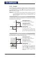
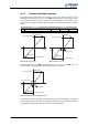
Depending on the behavior of the motor after start, carry out the following steps:
−
Motor does not turn, or the motor shaft only turns to a new position and
stops again:
• Check if the parameters No. of Pole Pairs 373 for the motor and
N
o. of Pole
Pairs
381 for the resolver are set correctly.
If these values are adjusted correctly, take the following measures complying with
the safety instructions.
Warning! The mains, direct voltage and motor sockets can be live with dangerous
volta
g
e after disconnection of the frequency inverter. Work only on the
device after a waitin
g
period of some minutes until the DC link capacitors
have discharged.
• Before electrical installation work, de-ener
g
ize the frequency inverter and take
appropriate precautions to make sure it is not re-ener
g
ized unintentionally.
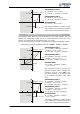
Make sure that the frequency inverter is de-energized.
• Exchange two motor phases (e.g. U and V) at the frequency inverter sockets
because the senses of rotation of the motor and the resolver do not correspond
to each other.
• Switch on the power supply again.
• As described above, adjust a low speed reference value and start the motor.