
Operating instructions

60 08/06
If the motor does not start despite the phase exchange:
• increase the parameter value for Offset 382 by 90°, divided by the no. of motor
pole pairs.
If the motor still does not turn, exchan
g
e the two motor phases (e.
g
. U and V)
again.
− The motor turns and accelerates until it reaches the Frequency Switch-Of
f
Limit
417:
• Check the resolver lines and check the resolver connection contacts.
• in the case of fault messa
g
e "Overfrequency" F1100: increase the paramete
r
value for Offset 382 by 180°, divided by the no. of motor pole pairs.
− If the motor turns at the ad
j
usted speed and in the ri
g
ht direction, carr
y
out the fine adjustment of the offset:
• Adjust the parameter value for Offset 382 in small steps (e.g. 2.5°) until the
flux-forming voltage 235 is approximately 0.
− In case the flux-forming voltage deviates from 0 significantly, adjust the offset
in bigger steps.
− In the case of a positive flux-forming voltage, increase the offset.
− In the case of a negative flux-forming voltage, reduce the offset.
• Adjust parameters Frequency Switch-Off Limit 417 and Current Limit 728 to
the required values.
• Repeat the fine adjustment of the offset at 50% of the rated frequency.
This completes the offset adjustment.
• Start the guided commissioning. This is required for optimum current control.
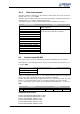
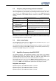
5.2.2 Actual speed source
Switch-over is effected via Actual Speed Source
766. If the resolver delivers the actual
value signal for the speed controller, speed sensor 2 must be selected as the source. In
the basic setting, speed sensor 1 is used as the actual value source.
Operation mode Function
1 -Speed sensor 1
The actual speed source is speed sensor 1 of the
basic device (factory setting).
2 -Speed sensor 2
The actual speed source is speed sensor 2 of the EM-
RES-02 expansion module.