9 REACH IN BLAST CHILLER AND FREEZER BIOTRONIC TURBO Electronic Regulation CHILLER AND FREEZER : MI 3, MI 6, MI 10 TECHNICAL MANUAL INCLUDING - USER MANUAL - INSTRUCTIONS BONNET GRANDE CUISINE Rue des Frères Lumière - Z.I. Mitry Compans 77292 MITRY MORY cedex Tél. 01 60 93 70 00 - Fax.
RECTO
USER MANUAL REACH IN BLAST CHILLER AND FREEZER BIOTRONIC TURBO Electronic Regulation CHILLER AND FREEZER : MI 3, MI 6, MI 10 CONTENTS Important recommendations 2 1. Use of the control panel 3 2. Use 10 3. Maintenance 11 4. Operation anomalies 12 BONNET GRANDE CUISINE Rue des Frères Lumière - Z.I. Mitry Compans 77292 MITRY MORY cedex Tél. 01 60 93 70 00 - Fax.
IMPORTANT RECOMMENDATIONS ∗ This unit is designed for use in Restaurants or Catering facilities. It is not intended for industrial use. ∗ Installation should be undertaken by a refrigeration engineer. ∗ Avoid installing the unit near major sources of heat or in direct sunlight. ∗ Note that too high an ambient temperature can reduce performance. ∗ The compressor condenser must be cleaned regularly (every 3 to 6 months) by a refrigeration engineer.
1. USE OF THE CONTROL PANEL 1.1 IMPORTANT Stop of the unit does not cut the power supply to the appliance. If the appliance is not to be used for a period of time, power must be cut off with the insulation switch located on the control panel’s side, the plug or the disconnector because of the risk of dammaging the refrigerating equipment. 1.
1.3 GENERAL RECOMMENDATIONS 1.3.1 DEFROST, PREFUNCTION CYCLE Before loading products, a prefunction cycle should be launched in order to cool the interior of the appliance. It can be launched automatically when the appliance is powered up, by modifying the factory settings (see ‘instructions’). Each prefunction cycle is automatically preceded by a defrost cycle. If needed, this function can be stopped (see paragraph 1.
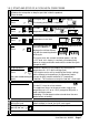
1.4 SIMPLIFIED GUIDE with factory settings POWER UP Press on Press for a few seconds. ) PREFUNCTION CYCLE Press on To select the cycle Press on to start the cycle. A defrost cycle is launched and automatically followed by a prefunction cycle. ) LOADING At the end of the prefunction cycle, introduce the products into the appliance. For a core probe cycle, introduce the core probe deep inside the product.
1.5 DETAILED GUIDE 1.5.1 START (Prefunction cycle) 1) All the leds as well as the display light up (Microprocessor test) 1 Power up Press for a few ) seconds 2) The machine number pre programmed during installation lights up. 3) The ON led lights up and the temperature of the compartment is displayed. 2 Selection and start This stage can be launched automatically when the appliance is powered up, by modifying the factory setting (parameter 03). The ‘Prefunction cycle’ led lights up.
1.5.2 START AND STOP OF A CYCLE WITH CORE PROBE 1 Open the door and introdu e the products to be cooled. Introduce the core probe as deep as possible inside the products. Close the door 2 Selection : The cycle and ) Press 3 Mode : Press or 4 Settings (eventual) : Press ) or 5 Start : Press or light up, the factory pre set temperature is displayed or To modify the end of cycle set-point.
1.5.3 START AND STOP OF A CYCLE WITH TIMER 1 Open the door and introduce the products to be cooled. Check the core probe is well installed on its support. Close the door. 2 Selection : The Cycle and ) Press 3 Mode : Press or 4 Settings (eventual) : Press ) or 5 Start : Press or freezing leds light up, the factory pre set cycle duration is displayed. or To modify the cycle duration.
1.6 SPECIAL SETTINGS 1.6.1 PROGRAMMATION (The regulation is ON) 1 Access to programmation : Press simultaneously and for a few seconds Beginning of the programmation mode. ) Display of the parameters one after another.
1.7 ALARMS AND DEFECTS Indicated by the red led and the sound alarm The display indicates the type of defects The buzzer can be stopped by pressing ) 1.7.1 USE SECURITIES The core probe is not or not well introduced in the product. The door is open. The normal time is over. Supply breakdown. 1.7.2 OPERATION DEFECTS (call for the repairer) Regulation probe defect. Core probe defect. Refrigerating defect.
2. USE 2.1 GENERAL REQUIREMENTS Do not load products in a way that obstructs the air circulation, this is important to ensure even distribution of cold air within the cavity. When the probe is not used, it must be located absolutely on its support. When the appliance is not used, it is recommended to let the door half-open. 2.2 LOADING A space of at least 15 mm is required between each item to allow refrigerated air to pass around the products.
3. MAINTENANCE IMPORTANT Before any cleaning operation, ensure that the appliance is unplugged. Do not use a spray hose in order to avoid water spattering 3.1 STAINLESS STEEL Use warm soapy water or a non corrosive cleaner (such as Teepol or an equivalent product) then rinse thoroughly and dry. Do not use abrasive, aggressive or concentrated cleaning products. Do not use wire wool under any circumstances. Fingerprints can be removed with a cloth soaked in alcohol. 3.
4. OPERATION ANOMALIES In case of abnormal operation and before the intervention of the aftersales service, Findings Causes, Checkings and solutions Impossible to switch on the appliance with Electric supply cut. - Check the connection of the supply the On/Off switch. cable - Check the fuses and/or the circuitbreaker located before the power plug. Power cut of the area Complete stop of the appliance during a - Check the fuses and/or the circuitcycle. breaker located before the power plug.
INSTRUCTIONS REACH IN BLAST CHILLER AND FREEZER BIOTRONIC TURBO Electronic Regulation Chiller and freezer : MI 3, MI 6, MI 10 CONTENTS Important recommendations 2 1. Technical data 3 2. Installation 5 3. Operation 8 4. Interventions and repairs 10 5. Electrical diagrams 14 6. Spare parts 17 BONNET GRANDE CUISINE Rue des Frères Lumière - Z.I. Mitry Compans 77292 MITRY MORY cedex Tél. 01 60 93 70 00 - Fax.
IMPORTANT RECOMMENDATIONS ∗ When installing the appliance, ensure that there is adequate circulation and air volume to cool the condenser and compressor. ∗ Avoid installing the appliance near major sources of heat, or in direct sunlight. ∗ Note that too high an ambient temperature can reduce performance. ∗ There must be earth continuity between the appliance and the mains connections. ∗ The supply cable that is fitted is a specific part and should only be replaced with an original part.
1. TECHNICAL DATA 1.1 MI 3 Type S216A15 MI 3 CONSTRUCTION Austenitic stainless exterior casing (sides, rear, front panel, and door) and interior lining. Bottom of the exterior casing and refrigeration unit frame in corrosion proof galvanised sheet. Austenitic stainless door liner. Insulated body - Monocoque type. - Radiused interior lining bottom and sides. - Polyurethane foam insulation, 50 mm thick. - Thermal break between inner and outer structure.
1.2 MI 6 Type S107D52 MI 6 CONSTRUCTION Austenitic stainless exterior casing (sides, rear, front panel and door) and interior lining. Bottom of the exterior casing and refrigeration unit frame in corrosion proof galvanised iron. Austenitic stainless door liner. Insulated body - Monocoque type. - Radiused interior lining bottom and sides. - Polyurethane insulation foam, 50 mm thick. - Thermal break between inner and outer structure. - 4 adjustable legs (or optional casters).
1.3 M 10 Type S120D52 MI 10 CONSTRUCTION Austenitic stainless exterior casing (sides, rear, front panel and door) and interior lining. Bottom of the exterior casing and refrigeration unit frame in corrosion proof galvanised iron. Austenitic stainless door liner. Insulated body - Monocoque type. - Radiused interior lining bottom and sides. - Polyurethane insulation foam, 50 mm thick. - Thermal break between inner and outer structure. - 4 adjustable legs (or optional casters).
2. INSTALLATION 2.1 GENERAL REQUIREMENTS The appliance must be installed, modified and repaired by a specialized engineer in accordance with current regulations. 2.2 HANDLING The appliance must be handled with suitable lifting equipment, transported on its original pallet and not stacked. If moving the appliance without its pallet, it must be carried and not pulled. 2.3 UNPACKING AND INSTALLATION 2.3.
2.3.3 CONNECTIONS ELECTRICAL See paragraph 1 ‘’Technical data’’ The appliance is fitted with a supply cable that should not be removed. This unit must be earthed (see recommendations). A circuit-breaker or suitable fuses should be provided on the supply. DEFROST WATER The collection tray can be replaced by a tube outlet (Tube PVC Ø32 not supplied).
3. OPERATION 3.1 GENERAL REQUIREMENTS Ensure that the fans are not obstructed. If the appliance has been laid down during transport or handling, wait 24 hours before use to allow refrigerant oil to return to the compressor. 3.2 PRESENTATION OF THE CONTROL PANEL Leds Defrost cycle Core probe and/or prefunction cycle cycle Cycle Led with timer Display - Temperature - Duration (h.
3.3.2 ACCESS TO PARAMETERS The appliance is ON : 1 Access to level 1 : Beginning of the programmation mode.
3.3.
TABLE OF PARAMETERS (2nd part) Code Parameters Min Max Fact.
4. INTERVENTIONS AND REPAIRS IMPORTANT Before any operation, ensure that the appliance is unplugged. 4.1 ACCESS TO COMPRESSOR UNIT To clean the condenser f, to access the unit and the electric box e remove the control panel grid h. 4.1.1 MI 3 MODEL 1) Unscrew the 2 screws g 2) Remove the grid h following c andd 3) Remove the condenser fan i by cutting the 2 "rilsan" rings 4) Clean the condenser f with a non metallic brush with soft hair 5) Refix the fan with , 2 "rilsan" rings on the condenser cross. 4.
4.2 ACCESS TO THE EVAPORATOR The access to the evaporator (access to the expansion valve e) is possible by pivoting the fan support c once the screw (or screws) d is unscrewed. To obtain a maximum opening of the fan support, the interior lining should be removed. (See paragraph 3.2 of the user manual) 4.3 REPLACING OF THE DOOR To replace or reverse the door opening. 1) Remove the grid i (see paragraph 4.
4.4 REPLACING OF THE PROBE 1) Unscrew the male connector c from the female connector e located under the top g of the appliance. 2) Replace the core probe d Nota : The surmoulded connector e is located in a box f in the top insulation g. To replace it, it is necessary to make a connection with the cable introduced in the appliance insulation.
5. ELECTRICAL DIAGRAMS 5.1 PRINCIPLE DIAGRAM FOR MI 3 N° SE146 Afficheur : Display card Micro. : Electronic card Exten. : Extension card Sd.A : Ambient probe Sd.P : 5 point core probe Ip : Door switch KMg : Group contactor coil Kmg : Group contactor Cp : Compressor R carter : Casing resistance Vc : Condenser fan Ve : Evaporator fan C : Condensator The installer is responsible for protecting the appliance against overloads or electrical defects.
5.2 PRINCIPLE DIAGRAM FOR MI 6 N° SE147 Afficheur : Display card Micro. : Electronic card Extens. : Extension card Sd.A : Ambient probe Sd.P : 5 point core probe Ip : Door switch HP : Pressostat KMg : Group contactor coil Kmg : Group contactor f1 : Thermal relay Cp : Compressor R carter : Cp casing resistance Vc : Condenser fan Ve : Evaporator fan C : condensator The installer is responsible for protecting the appliance against overloads or electrical defects.
5.3 PRINCIPLE DIAGRAM FOR MI 10 N° SE148 Afficheur : Display card Micro. : Electronic card Extens. : Extension card Sd.A : Ambient probe Sd.P : 5 point core probe Ip : Door switch HP : Pressostat KMg : Group contactor coil Kmg : Group contactor f1 : Thermal relay Cp : Compressor R carter : Cp casing resistance Vc : Condenser fan Ve : Evaporator fan C : Condensator The installer is responsible for protecting the appliance against overloads or electrical defects.
6. SPARE PARTS 6.1 CASING MI 3 MI 6 MI 10 z z S061P02 S630PM42 S630PN42 S630PO42 S062P02 S631PM42 S632PM42 S633PM42 Slides support brace axis Stainless slides support brace H. 328 --- " --H. 728 --- " --H. 1073 Slides support alu axis stainless slides support H.315, 3 levels pitch 80 --- " --H.715, 6 levels pitch 100 --- " --H.1060, 10 levels pitch 100 z S631PN42 S632PN42 S633PN42 Probe support slides support H.315, 3 pitch 80 --- " --H.715, 6 pitch 100 --- " --H.
CASING (2nd part) MI 3 MI 6 MI 10 z Condenser fan support (part) ∅ 310 --- " --∅ 380 Rubber fan support plate hinges Evaporator fan support plate hinges alu washer Fan support plate hinges alu pin Triangle button screw for support plate fixing Evaporator rubber bib H. 70 --- " --H. 90 --- " --H.
REFRIGERATING ELECTRIC COMPONENTS (2nd part) MI 3 MI 6 MI 10 z Evaporator ---"-----"--- z z S126P20 S137P20 S138P20 S139P20 S162P15 Expansion valve Nozzle ---"-----"--Evaporator fan z S862PA54 S863PA54 S864PA54 Electric box set ---"-----"--- z z S896PA54 S898PA54 Control panel set ---"--- z z z z z z S102P15 S076P15 S100P15 S115P15 Compressor contactor LC1D1210M7 LA1DN11 Auxiliary contact Thermal relay LR2D1310 ---"--LR2D1314 z z z z z z z z z z Designation S003P30 S004P30 S005P30
Instructions n°648261 - Page 1
DECLARATION DE CONFORMITE CONFORMITY DECLARATION HERSTELLERKONFORMITÄTSERKLÄRUNG TYPE / TYPE / TYP N° DE SERIE / SERIAL N° / FAB Nr : : Cet appareil est conforme aux dispositions de la directive « Basse tension » 73/23/CEE et de la directive « Compatibilité électromagnétique » 89/336/CEE. This appliance complies with the provisions of the low voltage directive EEC/73/23 and with the provisions of the electromagnetic compatibility directive EEC/89/336.