
User manual


Instructions n°648261 – Page 11
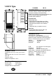
TABLE OF PARAMETERS (2
nd
part)
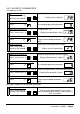
Code Parameters Min Max Fact.
F = VENTILATION
F0 Ventilation ON in preservation cycle
0 = weak, 1 = strong
010
(2) F1 Ventilation ON with fragile products
0 = weak 1 = strong
011
F4 Ventilation ON in defrost cycle
0 = weak, 1 = strong
010
F5 Ventilation rythm after draining 0 15 0
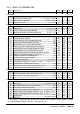
u = OUTLET ASSIGNATION
u0 RL1 relay operation
0 = on/off, 1 = alarm
011
u1 RL1 relay polarity
0 = NO, 1 = NC
010
i = PRINTER
i0 Printer presence
0 = no, 1 = yes
010
(2) i1 Printing frequency in chilling cycle
(mn)
0605
(2) i2 Printing frequency in preservation cycle
(mn)
06030
(2) i3 Printing at the beginning of the cycle
0 = no, 1 = yes
011
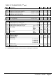
(2) i4 Date setting Day 1 31
(3)
(2) i5 Month 1 12
(3)
(2) i6 Year 990 050
(3)
(2) i7 Time setting Hour 0 23
(3)
(2) i8 Minute 0 59
(3)
L = NETWORK
L1 Instrument address 1 15 1
L2 Instrument group 0 7 0
L3 Timeout link 2 250 7
L4 Transfer rate
0 = 1200 bauds
1 = 2400 bauds
2 = 4800 bauds
3 = 9600 bauds
031
L5 Machine code A Y
(3)
A
L6 Machine number 1 99
(3)
1
(2) : Configuration parameters on level 1, accessible to user.
(3) : Configuration parameters which must be set during the installation.