4540 Series RF Power Meters Quick Start Guide V 1.
4540 Power Meter Quick Start Guide CONTENT SAFETY SUMMARY 3 LIMITED WARRANTY 4 4540 GETTING STARTED 5 CONTROLLING THE 4540 POWER METER REAR PANEL 6 12 4540 OPERATION INITIALIZATION CALIBRATION UPDATING FIRMWARE MENU TREES 15 15 16 18 19 POWER MEASUREMENTS MODULATED MODE PULSE MODE STATISTICAL MODE 28 28 30 32 4540 SPECIFICATIONS 34 ORDERING INFORMATION 35 4540 SENSORS PEAK CW SENSOR COMPATIBILITY 37 37 38 39 GLOSSARY 40 CONTACT 42 PN: 98406000A © Copyright 2008 Boonton Page 2
4540 Power Meter Quick Start Guide SAFETY SUMMARY The following general safety precautions must be observed during all phases of operation and maintenance of the Boonton 4540 RF Power Meter. Failure to comply with these precautions or with specific warnings elsewhere in this manual violates safety standards of design, manufacture, and intended use of the instruments. Boonton Electronics Corporation assumes no liability for the customer’s failure to comply with these requirements.
540 Power Meter Quick Start Guide LIMITED WARRANTY Boonton Electronics warrants its products to the original Purchaser to be free from defects in material and workmanship and to operate within applicable specifications for a period of one year from date of shipment for instruments, probes, power sensors and accessories. Boonton Electronics further warrants that its instruments will perform within all current specifications under normal use and service for one year from date of shipment.
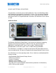
4540 Power Meter Quick Start Guide 4540 GETTING STARTED Congratulations and thank you for choosing Boonton. Your new 4540 Power Meter ranks among the most powerful instruments in its class. Our new family of Boonton CW and Peak Power Meters currently consists of the single channel 4541 and the dual-channel 4542. For simplification both instruments are referred to in this manual as 4540.
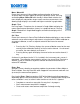
4540 Power Meter Quick Start Guide CONTROLLING THE 4540 On / Standby Pressing the On/Standby key switches the power meter between on and standby modes. When in standby, some circuitry remains powered to reduce drain on the battery used to maintain the instrument’s realtime clock. The instrument’s current operating state is automatically saved before entering standby. Control Keys Control keys allow maneuvering through the menus of the 4540.
4540 Power Meter Quick Start Guide Menu / Menu Off Places the instrument in Menu Mode to allow navigation of the menu structure. Menu soft keys appear at the right side of the screen. Pressing and holding Menu / Menu Off while already in Menu Mode switches the menu display off and provides larger screen area for measurements, thus allowing larger display in text mode and higher resolution in graph mode.
4540 Power Meter Quick Start Guide Measurement Channels 4541 consists of one, 4542 of two measurement channels. Both systems are optionally available with the sensor and calibrator connectors located on the rear panel. Such a configuration can be beneficial for rack mount ATE applications The measurement channels provide an RF range from 1 MHz to 110 GHz and offer a dynamic range of -55 dBm to +20 dBm for Peak Power measurements and -70 dBm to +44 dBm for CW Power measurements.
4540 Power Meter Quick Start Guide Soft keys The five Menu Soft Keys are used to navigate the menu hierarchy and to view or modify instrument settings. These keys are active only when the menu is displayed. Each key has a corresponding “menu box”, that changes depending upon which menu is visible. Pressing the soft key may perform any one of several operations, depending on the particular menu.
4540 Power Meter Quick Start Guide Up and Down Arrow Keys Pressing the ▲ or ▼ key performs ONE of the following prioritized operations, depending upon the current instrument state. The list is evaluated from the top, and once a condition is met, its action is taken and the rest of the list is ignored. • • • • Increments or decrements a numeric entry menu parameter, either by a default value, or by one digit place when in digit editing mode.
4540 Power Meter Quick Start Guide Numeric Entry There are three ways to modify the value of a selected numeric menu item. • Default Increment/Decrement – Pressing the ▲ or ▼ keys will increment or decrement the parameter by a default value. In most cases, this default is fixed. At other times, it may depend upon the current state instrument state, such as the display or time base settings. If the key is held, the increment/decrement will auto repeat slowly, then at an increasing rate.
4540 Power Meter Quick Start Guide 4540 Rear (Interface) Panel Main Power Switch The 4540 accepts any AC power from 90 to 264 V (47 to 63 Hz). No voltage switching is required. Power consumption is maximal 70 VA. Switching the power on sets the 4540 into Standby-Mode. To start the instrument, press also the green [On] button at the front panel. The fuse is a 1.0 A T type. Never use different fuses than specified. Damage may occur. Fan The 4540 Power Meters is an instrument designed for performance.
4540 Power Meter Quick Start Guide Rear Panel Measurement and Calibrator Connectors (Optional) The 4540 can be ordered with measurement channel(s) and/or the calibrator output mounted on the rear panel. This is usually handy when the instrument is integrated in systems like ATE. Communication interfaces. 4540 comes standard with LAN (Ethernet), USB and GPIB interface. All interfaces can be used to remote control the instrument.
4540 Power Meter Quick Start Guide VGA Out Information displayed at the front screen is also provided at the VGA Out interface. VGA out allows to connect any VGA, SVGA and XVGA monitors. The resolution is equivalent to the 4540 screen resolution 320 x 240 pixels. Trigger In When [Trigger Source External] is selected, power measurements can be triggered by external events. The trigger level can be set between 5V and +5 V, thus supports a variety of logic level signals.
4540 Power Meter Quick Start Guide 4540 OPERATION INITIALIZATION The procedures presented in this section will initialize the Boonton 4540 and prepares it for operation. Steps 1 through 3 should be performed every time you turn on the instrument. Step 4 only needs to be performed when you wish to return the instrument operation to a known state. This usually occurs after turning the instrument on or at the beginning of a new test. Step Procedure 1.
4540 OPERATION CALIBRATION Power sensors require calibration before they can be used. Calibration ensures most accurate power measurements. The 4540 Power Meter reminds users when sensor calibration is due. This can happen if it has not yet performed or after a period of time in which temperature changes may have occurred. The 4540 comes with a built in calibrator but also allows for utilizing an external calibrator. To prepare for the internal calibrator, ensure that the following settings are selected. 1.
4540 Power Meter Quick Start Guide Performing Calibration 1. Connect the sensor 1 to Channel 1 of the 4540. 2. Connect the sensor 2 to Channel 2 of the 4540 – if applicable. Note: To ensure accurate calibration of Peak power sensors it is strongly recommended to allow a warm-up and stabilization period of at least 3 minutes, after a sensor has been connected to a powered-on instrument. For best possible calibration we recommend to extend this period to 15 minutes. Calibrating Sensor 1 3.
4540 Power Meter Quick Start Guide 4540 OPERATION FIRMWARE UPDATE The Firmware of the 4540 is updated periodically. New firmware versions are free and can be downloaded from our Web site. Firmware of 4540 Power Meters can be easily field updated via USB, Ethernet or GPIB Bus. Requirements: PC Web access to download the firmware USB: USB cable (V1.1 and V2.
4540 Power Meter Quick Start Guide 4540 OPERATION MENU TREES Boonton’s 4540 is a designed for best performance but at the same time for ergonomic aspects and user convenience. Thus, menus of the systems are not rigid but take particular configurations and measurement conditions into account, this includes measurement modes and sensors connected. Also the sensor type, CW or Peak, determines different menu presentation.
4540 Power Meter Quick Start Guide MENU TREE: MAIN Main Channel Measure Channel 1 et sqq.“Channel” tree Channel 2 et sqq.“Channel” tree On / Off Mode Pulse | Modulated | Statistical Clear Single Sweep Auto Setup Trigger Mode Auto Pk-Pk | Auto | Normal | Free Run Source Level Num. Input: -50 to + 20 dBm Slope +|- Hold off Time * Time Base Position or Trig delay Position Cntrl Stat * More CH 1 | CH 2 | Ext Num. Input: 0 us to 1s (0.01us resolution) Num.
4540 Power Meter Quick Start Guide MENU TREE: CHANNEL Channel On / Off Vert. Scale, Up/Dn: 0.1 to 50 dB / Div Vert. Center, Num. Inp. : -100dBm to +100 dBm Calibration AutoCal: Start Fixed Cal: Start Zero Cal: Start Sel. Calibrator: Int | Ext Cal. Control Cal. Output: On/Off or On | Off CW | Int Pls | Ext Pls Level, Num Inp: -60.0 to +20.0 dBm Sel. Calibrator: Int | Ext Status Displ: Select Pulse Polarity: + / Duty Cycle: 10% to 90% Period: 100us | 1ms | 10 ms Preset or Polarity: + / Puls Width: 0.
4540 Power Meter Quick Start Guide MENU TREE: CHANNEL / EXTENSIONS Channel Units: dBm | Watts | Volts | dBV | dBmV | dBuV Extensions Corrections dB Offset, Num Inp.: +/- 200 dB Frequency Cal Factor, Num Ino.: +/- 3.00 dB Temp Comp: On | Off 1 Filter State: On | Off | Auto or 2 1 Averaging, Up/Dn: 1 to 16384 Filter Time: 0.000 to 16.000s or 2 Define Pulse Distal: 0.00 to 99.99% Mesial: 0.00 to 99.99% Proximal: 0.00 to 99.
4540 Power Meter Quick Start Guide MENU TREE: MAIN / STAT MODE Main Channel et sqq.“Channel” tree Measure et sqq.“Main / Measure” tree Trigger Stat Mode Only for Non-Stat-Mode Horiz. Scale Num. Input Up/Dn: 0.1 to 5 dB / Div Horiz. Offset Num. Input: -50.00 to +50.00 dB Term Options Term Action: Decimate | Stop | Restart Term Count: Num Input: 0.1 to 4000 MSa TermTime, Num Input: 0s to 3600s Cursors Cursor Mode: Percent | Power Ref Cursor Percent: 0.0000 to 100.0000% Cursor Power ref: 0.
4540 Power Meter Quick Start Guide MENU TREE: MAIN / MORE Main / More Markers 1 Marker 1 Position – Num. Inp.: -1s to + 1s (0.1ns increments) Delta Time - Display only or Marker 2 Position – Num. Inp.: -1s to + 1s (0.1ns increments) 2 Cursors Cursor Mode: Percent | Power Ref Cursor Percent: 0.0000 to 100.0000% Cursor Power ref: 0.000 to 200.000 dBr Display Key Beep: On | Off Graph Header Num. Rows: Up/Dn: 0 to 5 Edit Field Up/Dn: 0 to 9 Field Param. et sqq.
4540 Power Meter Quick Start Guide TABLES MENU TREE: MAIN / MORE Field Param CH 1 Source CH 2 Source TABLE TABLE TABLE Options Sec. Field 1 & 2 TABLE Field Parameter CH1 Source CH2 Source Options Sec.
4540 Power Meter Quick Start Guide MENU TREE: MAIN / MORE / SETUP Main / More Markers Display Setup Factory Defaults User Presets Save Recall Rename Delete Auto Setup Presets GSM EDGE NADC Bluetooth cdmaOne W-CDMA CDMA2000 iDEN RADAR MCPA WiFi 802.11a 802.
4540 Power Meter Quick Start Guide MENU TREE: MAIN / MORE / SYSTEM Main / More Markers Display Setup System GPIB I/O Config Ethernet Calibrator Cntrl. Cal. Output: On/Off or On | Off CW | Int Pls | Ext Pls Level, Num Inp: -60.0 to +20.0 dBm Sel. Calibrator: Int | Ext Status Displ: Select Pulse Polarity: + / Duty Cycle: 10% to 90% Period: 100us | 1ms | 10 ms Preset or Polarity: + / Puls Width: 0.000ms to 66.000 ms Puls Period: 0.000ms to 132.000 ms Variable Config.
4540 Power Meter Quick Start Guide POWER MEASUREMENTS What you need to know To perform accurate measurements, the following is a minimum list of things you should know about the signal that you wish to measure. Signal frequency - The center frequency of the carrier must be known to allow sensor frequency response compensation. Modulation Bandwidth - If the signal is modulated, know the type of modulation and its bandwidth.
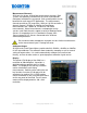
4540 Power Meter Quick Start Guide The measured result is the average power of the signal. Since the graphic display would basically just show a straight line, measurements in Modulated Mode use mainly the Numeric Display Mode. The example shows a two channel measurement displaying an average power of -29.952 dBm at CH 1 and 40.030 dBm at Ch 2. Examples of Modulated Signals CW Signal – Continuous Waveform with static power level Amplitude Shift Key – Signal switches between On and Off State.
4540 Power Meter Quick Start Guide PULSE MODE If pulses are rectangular, and the pulse width as well as the duty cycle is known, Modulated Mode measurements can be sufficient to determine the pulse power. For example GSM is a TDMA Pk Pwr = PAvg / Duty Cycle technology with one timeslot (PT1) out of eight (8) possible ones . P Pulse Width (PW) Modulated Mode measurement Pk Pwr would show an average value. This Pulse Repetition Interval (PRI) would allow to calculate the power of this particular timeslot.
4540 Power Meter Quick Start Guide Pulse Mode is only available when using a peak power sensor, and is best choice for most pulse modulated and periodic signals. Multiple modulation cycles may be averaged together, and measurement intervals may span both before and after the trigger. Pulse Mode is best for the following types of measurements: • • • • PN: 98406000A Moderate signal level (above about -40dBm except when modulation is “off”). The signal is periodic.
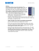
4540 Power Meter Quick Start Guide STATISTICAL MODE Certain signals are completely random and provide no event that can serve as a trigger for measurements. CDMA or OFDM are common examples. Such signal “randomness” places a challenge to measurements but the Statistical Mode of the 4540 offers an easy solution. Statistical Mode is only available when a peak power sensor is connected to the 4540. It is the best choice for analyzing “noise-like” signals that are modulated in a random, non periodic fashion.
4540 Power Meter Quick Start Guide CCDF Complementary Cumulative Distribution Function. The CCDF is the probability that the power is greater than a specific power value. CCDF is non-increasing in yaxis and the maximum power sample lies at 0%. In a non-statistical peak power measurement the peak-to-average ratio is the parameter which describes the headroom required in linear amplifiers to prevent clipping or compressing the modulated carrier.
4540 Power Meter Quick Start Guide 4540 SPECIFICATIONS Sensor Inputs RF Channels RF Frequency Range Peak Pwr range CW Pwr range Relative Offset Range Single Shot Bandwidth Video BW Rise Time 1 or 2 1 MHz to 110 GHz* -55 to +20 dBm* -70 to +44 dBm* ±200.00 dB 5 MHz (based on 10 samples/pulse) 70 MHz* 7 ns* * Sensor Dependent, Calibrator Dependent Acquisition and Measurement System Time resolution 0.
4540 Power Meter Quick Start Guide Modulated Mode Filtered Average, Peak and Min. (held or auto-decayed) User I/O Signals Sensors Calibrator GPIB Ethernet (LAN) USB device Recorder/Status Out Trigger In Pulse and Modulated Mode Marker Measurements Markers (Vertical Cursors) Settable in time relative to the trigger position Markers Independently Power at specified times (Avg., Peak, Min.) Pair of Marker Power at two specified times with ratio or average power between them.
4540 Power Meter Quick Start Guide ORDERING INFORMATION Power Meters 4541 RF Peak Power Analyzer, single channel, front panel inputs. 4542 RF Peak Power Analyzer, dual channel, front panel inputs Options -02 -03 -30 Rear sensor inputs Calibrator, rear panel output Warranty extended to 3 years Recommended Sensors Peak Power Model 57318 57518 Freq. Range 0.5 to 18 GHz 0.
4540 Power Meter Quick Start Guide 4540 RECOMMENDED SENSORS - PEAK Model Frequency Range Dynamic Range Overload Rating Sensor Response Impedance RF Connector (Low Bandwidth) Peak Pwr Rng CW Pwr Rng Int Trigger Rng Pulse / Continuous Fast Slow Rise Time Rise Time (Bandwidth) (Bandwidth) 57318 50 ohm N (M) 0.5 - 18 GHz (0.05 - 18 GHz) -24 to +20 dBm 1 W for 1µs -34 to +20 dBm 200 mW -10 to +20 dBm <15 ns(2) (35 MHz) 57340 50 ohm K (M) 0.5 - 40 GHz (0.
4540 Power Meter Quick Start Guide 4540 RECOMMENDED SENSORS - CW Model Frequency Range Dynamic Range Impedance RF Connector WIDE DYNAMIC RANGE DUAL DIODE SENSORS 51075A 50 ohm 500 kHz to 18 GHz -70 to +20 dBm N (M) 51077A 500 kHz to 18 GHz -60 to +30 dBm 50 ohm N (M) 51079A 50 ohm 500 kHz to 18 GHz -50 to +40 dBm N (M) 51071A 50 ohm K (M) 10 MHz to 26.
4540 Power Meter Quick Start Guide 4540 SENSOR COMPATIBILITY The table below shows a list of sensors that work with the 4540 Power Meter. Please note that the list includes also customized and legacy sensors, which are not at in the data sheet or in the price list. Please consider also that the minimum frequency of the 4540 is 1 MHz.
4540 Power Meter Quick Start Guide GLOSSARY CCDF Complementary Cumulative Distribution Function. Statistical Method to measure power of noise like signals, which have no pulse characteristic and offer no trigger event. This method compares probability in percent of signals that are lower than the highest measurement value. 4540 can sample a high number of data over a very long time to ensure virtually all occurring power levels are considered.
4540 Power Meter Quick Start Guide Warm-up (optimal) While a minimum warm-up and stabilization period of 3 mins is required, for best possible calibration and measurement accuracy we recommend connecting the sensor to the 4540 Peak Power meter with power switched on 15 mins before the calibration is initialized. Warm up and stabilization period is only required for Peak Power Sensors.
4540 Power Meter Quick Start Guide CONTACT Wireless Telecom Group Inc. Parsippany, NJ 07054 USA Tel: +1 973 386 9696 Fax: +1 973 386 9191 boonton@boonton.com www.boonton.com Wireless Telecom Group Cheadle Hulme, Cheshire United Kingdom Tel: +44 (0) 161 486 3353 Fax: +44 (0) 161 486 3354 boonton@boonton.com www.boonton.com Wireless Telecom Group Roissy France Tel: +33 (0) 1 72 02 30 30 Fax: +33 (0) 1 49 38 01 06 boonton@boonton.com www.boonton.