Contents 1 INTRODUCTION ........................................................................................... 7 2 SAFETY SUMMARY ..................................................................................... 8 3 4 5 6 2.1 SYMBOLS ............................................................................................... 8 2.2 DISCLAIMER ......................................................................................... 10 2.3 POWER REQUIREMENTS ...........................
7.2.10 Data Delete Log Files .................................................................. 44 7.2.11 Data Delete Carrier & Site............................................................ 46 7.3 System Menu ......................................................................................... 47 7.3.2 7.4 8 System Menu Functional Block ....................................................... 49 Analyzer Mode ....................................................................................
11 What is PIM? ............................................................................................. 77 11.1 11.1.1 Manufacturing & Design ............................................................... 77 11.1.2 Mechanical ................................................................................... 77 11.1.3 Environment ................................................................................. 78 11.2 12 What Causes PIM?......................................................
Manual Version Control ...................................................................................... 98 Contact .............................................................................................................
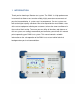
1 INTRODUCTION Thank you for choosing a Boonton test system. The PIM31 is a high performance instrument that allows users to make reliably, highly accurate measurements of passive intermodulation, in systems and / or components. Our test systems are built to the highest quality standards. We strive to provide the most reliable, state of the art test equipment allowing our customers to have the utmost confidence in the results of their testing.
2 SAFETY SUMMARY 2.1 SYMBOLS This safety requirement symbol (located on the rear panel) has been adopted by the International Electro-technical Commission, Document 66 (Central Office) 3, Paragraph 5.3, which directs that an instrument be so labeled if, for the correct use of the instrument, it is necessary to refer to the instruction manual. In this case it is recommended that reference be made to the instruction manual when connecting the instrument to the proper power source.
The following general safety precautions must be observed during all phases of operation and maintenance of the Boonton PIM 31 Passive Intermodulation Test System. Failure to comply with these precautions or with specific warnings elsewhere in this manual violates safety standards of design, manufacture, and intended use of the instrument. Boonton Electronics Corporation assumes no liability for the customer’s failure to comply with these requirements.
DO NOT SUBSTITUTE PARTS OR MODIFY INSTRUMENT Do not substitute parts or perform any unauthorized modification of the instrument. Return the instrument to Boonton Electronics for repair to insure that the warranty and safety features are maintained. NON IONIZING RADIO FREQUENCY RADIATION HAZARD This device generates Radio Frequency (RF) energy under normal operation, and should always be operated in accordance with local and national licensing laws.
2.3 POWER REQUIREMENTS The PIM 31 Series is equipped with a switching power supply that provides automatic operation from a 90 to 260 volt, 47 to 63 Hz, single-phase, AC power source. Maximum power consumption is 750W / 750 VA Caution For bench-top use, choose a clear, uncluttered area. For field use, choose a dust free environment.
2.4 PIM 31 SERIES PACKING LIST PIM 31 Series Test Systems are shipped complete and are ready to use upon receipt. Note Save the original packing material and container to reship the instrument, if necessary. If the original materials (or suitable substitute) are not available, contact Boonton Electronics to purchase replacements. Store packing materials always in dry environment. If frequent used in the field with we strongly recommend purchasing our PIM 31 Transit Case.
3 PIM 31 ELEMENTS 3.1 PIM 31 FRONT PANEL Number 1 2 3 4 Element Power Switch Description Function similar to a PC: one short push – PIM31 powers up, Another short push – controlled power down Holding it for 3 second – powers unit down immediately See also chapter Powering PIM31 up/down.
5 6 Audio Touch Screen Display 7 RF Power On 8 Front Panel Air Vents 9 Type Label is not in use. Loudspeaker for audio signals Touch screen display 800x600. Never use sharp devices to push buttons on the screen RF-Power light indicates when RF Power is present. Always allow for proper airflow, prevent alien objects or dust from being sucked in.
3.2 PIM 31 BACK PANEL Number Element 1 Main Power supply 2 Main Power Switch 3 4 5 VGA Port Communications port 10 MHz Reference out Air Flow Fan Air Flow Fan 6 7 Description AC Supply: 90-264V, 750W / 750VA use 90 deg connector only Fuse: 4A / 230V or 8A / 110V PIM31 contains protection circuitry to control RF Power during operation and during powering on/off cycles. After switching Main Power Switch On wait 2 seconds before pushing Front Power Button. Fans may Briefly run after power off.
4 PRECAUTIONS Caution DO NOT touch RF Connecting parts of components with bare fingers. Even the smallest amount of sweat on the conductors can cause oxidation, which will reduce the performance of the element and can cause PIM. Elements Included: • • • • • Caution RF Port of PIM31 Low PIM Cables Low PIM Load Low PIM Adapters All components in the transmitting path of the System under Test or DUT. DO NOT switch on RF power without load or antenna attached.
Caution DO NOT connect or disconnect any accessory or component of the test setup with RF power switched on. Even at low RF power levels, spark discharge can occur with sudden energy flow or flow disruption.. Spark discharge - must be avoided, because it will alter the surface of the pins and connection areas. “Burned” surfaces will not only reduce the performance of the component, but can also cause permanent PIM. Caution DO NOT operate test system and load without connector savers.
Caution DO NOT block air vents. Due to its high RF output power, PIM31 consumes up to 750W. This energy has to be disposed. While these test systems have protection against overheating, it is vital to keep air vents clear of any obstructions that would prevent or limit the air flow. Air vent locations • • • Front Panel Back Panel Bottom Keep clearance at least 15 cm / 6 inches for Front and Back Panel Vents, and 4cm / 1.5 for the bottom vent.
Caution DO NOT use sharp devices at the touch screen. Users can operate PIM31 test systems but utilizing the touch screen or via keyboard/mouse. The user interface is designed specifically for field use; all vital operations can be conveniently accessed via the touch screen interface. Do not use sharp devices; they can damage the touch screen. The touch screen, display and CPU are a single integrated module. In case of service the complete module has to be exchanged.
Keep Accessories clean: Dust and dirt may affect test results. Make sure accessories are stored properly and clean. Please use the protective caps - to keep the accessories free from contamination. Never use sharp devices to remove any contamination because scraping can cause metal chips in the contact areas, which will generate PIM. If any dirt, corrosion or any other foreign matter needs to be removed use special RF contact cleaning tabs and / or compressed air.
4.2 USING HIGH PERFORMANCE RF CABLES Cables are as vital to proper PIM testing as any of the other accessories are. Treat them with the appropriate care. All hints listed above for accessories apply to cables as well. Always use cable caps to protect connectors when the cable is not in use. The bending radius for the PIM31 cable delivered by Boonton is 20cm / 8 inches. To prevent damage, coil cable no tighter than 40 cm / 16 inches in diameter. A transit case for PIM31 systems is available.
5 POWERING PIM 31 UP/DOWN 5.1 Powering UP PIM 31 test systems power up in a similar fashion to a desktop PC. However, there is one exception: significant RF power has to be controlled and managed.. For this reason PIM 31 series test systems contain a protection system to protect the hardware, e.g. prevents unusual on/and off cycles ( e.g. 3 cycles per second). When used normally, the user will not even recognize that these protective mechanisms are working.
5.2 POWERING DOWN PIM31 can be powered down in different ways listed below. It is not recommended to power down simply by “Pulling the plug” or switching off the Main Switch on the back panel. Exiting The proper way is to Exit the UI is by pressing the red exit button. This will generate an exit pop up. Respond to the pop-up menu’s choice Yes / NO to power the system down or not.
“Pulling the Plug” This “method” should be avoided under all circumstances. It can damage the hardware and corrupt files. This “method” is especially critical if the RF port is still connected to a grounded system under test. Residual discharges may flow via RF Ground / Shield. With the main connector no longer plugged in, ground connection is also disrupted.
6 GETTING STARTED Before starting to measure components with PIM31 systems, users are urged to familiarize themselves with the precautions (Don’ts) in the chapter below. Improper operation and handling can cause bodily harm or damage the instrument. 6.1 THE FIRST MEASUREMENT Preparations: • • • Mount connector saver to RF Port and Load (if not already mounted) Connect Low PIM cable to Test system (Note: always connect the test cable to the instrument prior to connecting to the DUT) Connect Load to cable.
names help to recognize the settings: Example 20W_869_896 means: power of the signals is 20W, and the frequencies used are 869 MHz and 896MHz.Every entry or change needs to be confirmed by pushing the “Enter” button. Once our entries are complete, we return to the previous screen, “Carrier List” by pushing the green Return button. The list shows now a carrier entry. By pushing the Green return button we come back to the Field Mode screen.
PIM 31 test systems provide not only accurate PIM analysis, they also allow users to log data that is specific to a particular test setup or particular base station site. At a later point, measurements can be recalled for comparison and to analyze if the performance has changed. This particular information has to be entered as well. The process is similar to the Carrier entry, except this time we push the “Site” button. As with the carrier, the system lists all available Sites (or Tests).
By pressing the RF Button, the system initializes, and starts measuring PIM. A second push of the RF button stops measurements and transmission of RF signal carriers. The last PIM reading is held and shown in grey. Note: PIM 31 test systems switch RF Power off after 30mins (default). Other cycles or “Always On” can be selected. For more information refer to chapter System Menu.
7 PIM 31 OPERATION PIM31 Test Systems were developed to measure and analyze PIM data of RFcomponents, cables, or complete RF systems. Operation Modes for Different Applications: Field Mode / Analyzer Mode Depending on the application, the users’ requirements will be different. The main task at a base station site is to quickly analyze the RF Path, and document the measurements. If unacceptable PIM levels are detected the PIM31 can be used to identify and pin-point problematic components.
Similar conditions apply when components are tested. The instrument settings do not change, but for quality reasons every measurement has to be documented. For measuring RF Components, the Field Mode is a very comfortable and efficient If more detailed information about the DUT is required, it can be accessed by using the Analyzer Mode of the PIM31 test system.
7.1.1 Operations Menu Tree PIM 31 Test systems are designed to provide an efficient workflow. The Menu Tree shows the overall menu structure of the PIM31.
7.2 FIELD MODE 7.2.1 Field Mode Elements The following chapter describes the Display elements of the Field Mode screen. Element Name Description / Display A File Menue B Carrier Field:F1 C System management E Carrier Field:F2 F PIM Value dBm G IM Frequency H Status Indicator Field Pull down Menu, choices: “Quit”, same function as Exit Button See also chapter Pull-down Menus Shows Frequency (MHz) and Power level(dBm) of first carrier signal.
I RSSI J PIM Value dBc K Voltage Warning L Bar Graph PIM indicator M Display fields (3) Site, Feeder, Sector N RF On / Off Switch O P RF Indicator light System Q Audio On/Off R Analyzer S EXIT T Record U Carrier V Site W History X Data AUD – Audio On REC –Data Recording SPU – Soft Power Up RSSI (Received Signal Strength Indication) in dBm. External signals at the receiving frequency / frequencies may disturb PIM measurements.
and carriers) For more information see chapter Data Active only when RF-Power is OFF 7.2.2 Carrier Entry Carrier Signal settings specify the frequencies of the transmitting RF signals and their power level. Site information allows to a) specify the tested site in detail or to specify component tests more closely. All settings entered with Carrier signals or Site/Test information are recorded when measurement data is logged, this allows for detailed analysis after a series of tests has been completed.
Element Name Description / Display A Carrier B Selected Carrier C Page Indicator & Jump arrows D New E Edit F Return Carrier specific information on frequencies and power levels stored in the PIM31. The yellow background indicates the carrier that is selected and will be used for test after pressing Return If more than 6 different carrier signals are stored in the PIM31, the current page and number of pages are shown.
Element Name Description / Display A Carrier 1 Parameter B Carrier Name C Carrier 2 Parameter D ALC E F Return IM G 123 / ABC H Delete I Enter J Keyboard K L Space Capitals Sets power level and frequency of carrier signal 1: Note: when entering this field a numeric keyboard is displayed. A new or changed value is accepted by pushing the Enter button (I) When entering new carrier information, the cursor is set to this field and marked orange for editing.
7.2.3 Site Entry As with Carriers, Sites (or Tests) and linked information can be stored in the memory of the PIM31. Once Sites have been stored in the system, they can be easily recalled. The screenshot shows a list of 4 Sites with related information on feeder and sector. Element Name Description / Display A Site B Selected Site C Page Indicator & Jump arrows D New E Edit F Return Sites, with information on feeder and sector stored in the PIM31.
PIM 31 Site Edit Element Name Description / Display A B C Carrier Name Comment Site / Test Name D Sector E F Return Feed G User H 123 / ABC I Delete J Enter Carrier signal to which site information is related to. Allows additional entries related to the Site or Test. Site / test name New or changed entries are stored by pushing “Enter” (J) Additional information (Sector) New or changed entries are stored by pushing “Enter” (J) Returns to previous site.
K Keyboard L M Space Capitals Keyboard, toggles between characters and numeric Space Upper case entries Note: When using an external keyboard do not use commas in names or descriptions. Log Data is stored in a CSV (Commaseparated value) text form. Commas in the description will mix up fields that are assigned for particular values, relevant e.g. when importing data in a spreadsheet or database. The touch screen keyboard does not offer commas for entry. 7.2.
7.2.5 History Screen Log data is stored in the test system memory whenever the REC button is pushed. Log data stores the measurements, tester settings, and site related information. With this capability operators can view historic information of specific sites, allowing them to compare current and former measurements and analyze if their performance has changed over time..
7.2.6 Data Management The following chapter describes the Data Menu and Data structure. Recording / Record - Button PIM31 can store measurement data manually (default) or automatically with predetermined intervals. When the “Record” button in the “Field Mode” screen is pushed, the system stores one data set in a log file. The recorded measurement data is stored in a log file. This file is stored in ASCII text format with CSV structure.
Content (comma separated) Variable Format Date Time PIM (dBc) PIM (dBm) RSSI (dBm) F1 (MHz) F2 (MHz) IM 3 (MHz) F1 (dBm) F2 (dBm) IM3 Bandwidth (Hz) PIM 31 Type Model Serial Number HW Version SW Version OS Version Carrier Site Name Feeder User “Wireless Telecom Group” “PIM 31 Data Log” Cal date CHKSUM YYYYMMDD HHMMSS -XXX.X -XXX.X -XXX.X XXXX.X XXXX.X XXXX.X XX.X XX.
7.2.8 Log File Management All measurements are stored in separate log files. When transferring files to an external drive (e.g. memory stick), all log data is merged into one file for ease of importing into databases and spreadsheets. Default drive directory and file name of the merged log data-sets is: D:\Site Info\PIM31_Site_all.log The default setting can be overwritten when specific locations or filenames are required (requires keyboard). 7.2.
C Site D History E F Copy Site G Advanced H I Default Return Default: No Allows copying of log data from a specific Site or all Sites the PIM 31 contains. Specific Sites can be selected via the Site Button Selection: Specific, All Default: Specific Allows copying of log data recorded at specific dates Selection: Today, Specific, All, Date, Period Date or Period require entry in YY/MM/DD format. Press enter to store setting Default: Today Executes copy process Opens Site Selection screen.
Element Name Description / Display A Carrier B Site C History D Delete Selection to erase log data of a specific Carrier, All Carriers or none. Specific Carriers can be selected via the Carrier button Selection: None, Specific, All Default: None Selection to erase log data of a specific Site, all sites or none.
7.2.11 Data Delete Carrier & Site This Menu allows users to delete Sites and/or Carriers. After the deletion process, all Carrier and/or Site related settings and data, including log data, will be erased. Element Name Description / Display A Carrier B Site C Sites Only Sites & Carriers D Delete E Carrier Selection to erase a specific Carrier, All Carriers or none.
F Site G H Default Return Opens Site Selection screen. Marked Site on site Selection screen will be transferred to Data Site & Carrier Delete Menu after Return Sets default values Returns to Data Copy site. 7.3 System Menu The System Menu provides information about the PIM31 test system. Information shown includes software version, hardware version, and memory space available for log data. This menu allows users to modify the default settings of the PIM31.
Element Name Description / Display A B Model TX Frequencies C RX Frequencies Model type of PIMI31. . Transmitting frequency range, tester type dependent Receiving frequency range, tester type dependent D E F G H I J SW Version HW Version Operation System Free Space Cal Date Serial Number Basic / Advanced K L Default Return Software Version of PIM31 Hardware version of PIM31 Operation system and service pack used Memory space available for data logging.
7.3.1.1 PIM 31 Memory Space PIM 31 Passive intermodulation test systems come with a total of 5.75 GB of user accessible memory. This memory is used to store log data and site setup information. The average size of a Log data set is 250 Bytes. With a drive segmentation of 512 Byte per block, PIM 31 test systems can store more than 11 Million data sets. 7.3.2 System Menu Functional Block 7.3.2.1 RF ON TIME By default, PIM 31 test systems will switch RF power off after 30mins.
7.3.2.2 REC Interval PIM 31 test systems record measurements whenever the Record button is pushed. Multiple pushes create multiple, corresponding individual log files. If measurements need to be analyzed over a longer of time, PIM 31 test systems can record log data automatically by setting the REC interval to a value other than “OFF”, which will record data automatically at the interval entered.
7.3.2.3 Filter BW Advanced Mode Only. Default filter bandwidth of the PIM31 receiver is 1.2 kHz; which is the optimized setting for best performance. Increasing bandwidth opens the receiver, allowing to “see” if signals are present close to the receiving signal frequencies. If Change of Filter Bandwidth effects all IM frequencies that fall in the receiving range of the PIM31.Decreasing the filter bandwidth allows to eliminate unwanted signals very close to the receiving signal frequencies.
are prone to such reflections. If the returned energy is too high, PIM31 will switch off to protect its hardware. A remedy is to simply increasing RF power gradually. SPU Time: Increments 1s, Settings range 0sec to 60sec Default: 0s Example: With a power setting for 43dBm and SPU of 10s it takes 10 seconds to ramp RF power up from 20dBm to 43dBm Note: PIM31 starts measuring immediately after RF power is present at the RF Port.
7.3.2.5 BAR Graph G/R Advanced Mode Only The Bar Graph’s green/red threshold is -153dBc by default. The switch from green to red is an optical indicator if a DUT is within limits or if it exceeds them. PIM measurement values higher than the set threshold can provide an audible indicator. Obviously Audio has to be switched on in the Field Mode screen. Maxhold is an important feature which holds the maximum value during PIM measurements. In this example the maxhold value is -147 dBc.
Default: ON 7.4 Analyzer Mode The Analyzer Mode of the PM 31 offers more possibilities to analyze PIM measurements. It contains of 3 Sub modes: • • • Frequency Time Sweep The Analyzer mode is selected by pressing the Analyzer button while in the Field Mode Screen. Returning to field mode is possible by pressing the return button. RF Power needs to be OFF Frequency and power values can be set directly without utilizing Carrier or Site information.
Element Name Description / Display A Pull-Down menu B Carrier display C Graphical display D Zoom Out E F Tx/Rx RF Power Button G Return H Parameter Setting Allows Screenshots, data logging, and self test. For more information refer to chapter Pull-Down menus. Carrier signal information: Frequencies, Power levels Shows up to 4 IM signals as a vertical bar. Position on the x-axis indicates frequency and length indicates power level.
I Reference Line J Reference IM K Frequency L Time M Sweep N Numeric field 1 O Numeric field 2 P Numeric field 3 Q Numeric field 4 Moves reference line for audible indication of measurements that exceed the limit. Same as Green/Red threshold of Bar graph in field mode. Range -60 to -200 dBc Selects if particular IM products (faster) or All IM products (more comprehensive) that fall into the receiving band of the PIM31. The test system can show up to 4 IM signals at the same time.
7.4.2 Time Mode In Time mode IM products are displayed as a horizontally moving line, where the position indicates the power level over the time. This display is very helpful to test immediate PIM variations, like loose connections. Any change is immediately visible. Time mode shows a 10 seconds window, but more information up to 10 minutes may be recorded. Move past traces to the window by touching, holding and drawing it to right until the wanted information is appears.
7.4.3 Sweep Mode IM products in linear environment are frequency independent. Many passive components show a frequency response that is less linear or strongly frequency dependent. The sweep mode increments / decrements carrier signals by 1 MHz. covering a Tx range that results in a sweep of the complete Rx frequency range. Any deviations of PIM measurements that are frequency dependent are immediately visible.
D E F TX Range Tx/Rx RF Power Button G Return H Parameter Setting I Reference Line K Frequency L Time M Sweep N Hold O Single P Sweep Edit Q Freq Up/Down downwards –yellow trace. Increments are 1 MHz IM signals as a vertical bar. Position on the x-axis indicates frequency and length indicates power level. Color of the bars refers to the colors of the numeric displays (N-Q).
Element Name Description / Display A Reference IM B Freq 1 Sweep C Freq 2 Sweep D Sweep Cycle E Set Allows selection of IM product (in case more than one are in the swept range) Start Frequency of up-sweep Default: lowest Tx frequency the tester can generate Start frequency of down-sweep Default: lowest Tx frequency the tester can generate Time between setting and measurement of increments Stores settings and returns to Analyzer Sweep Mode Note: Sweep mode requires setting the power levels (Pa
8 Pull Down Menus Pull down Menus offer additional features and allow users to set some system parameters. They allow also performing a self test of the PIM31 test system. Three Pull-Down menus are available: • • File o Start History Save o Stop History Save o Screen Capture o Initialize Program o Quit System Management o Self Test o PIMD management o Connection check * Field Mode offers a subset of Pull-Down menus, Analyzer mode offers all of them.
8.1 File 8.1.1 Start / Stop History Save This feature allows users to log measurements over a period of time in Analyzer mode. The log files are stored in TSV (Tab Separated Value) ASCII text format.
8.1.2 Screen Capture / Print This menu provides capabilities to capture a screen shot from any Graphical Display of the Analyzer Mode. Capturing a screen shot requires manual trigger, entering a file name, drive and directory. By default, the file name consists of date and time, but can be modified by the user. The file is stored in jpeg format by pressing the blue save button. The stored file has a size of about 150kB.
8.1.3 Initialize Program Initialize should only be triggered if the system shows signs of irregular function. It sets system values to default values, manual settings may be lost. 8.1.4 Quit Quit has the same functionality as Exit in the Field Mode. The user will be asked if he really wants to quit the PIM 31. If answered YES, the system will power down.
8.2 System Management 8.2.1 Self Check Self check provides information about the PIM 31 test system. To allow the self check routine to test all modules, it needs to be performed with RF Power ON Name HPAx Output HPAx ON/OFF HPAx Temperature HPAx Over Power HPAx Temp Status Synthesizerx Lock HPAx Reverse Local Osc Lock Fan Operating Description RF Output power level (should be +/- 0.2 db within the set limits – ALC ON) Status of RF Power (ON/OFF) Temperature of amplifiers.
8.2.2 PIMD Management PIMD management allows setting some system and measurement parameters. With the exception of Sound On /Off, it is not required to change these settings. Name Equipment Selection Filter Bandwidth IM Level Sound SET CLOSE Description Not relevant for PIM31, since these provide only one frequency band. Default 1.2 kHz For further information refer to chapter “System Menu”. If ON, sound occurs when PIM level exceeds reference line.
9 Remote Application and TCP/IP Setup PIM31 Remote Control Panel is the software to control the PIM31 unit from any PC using a TCP/IP cable connection. This section explains how to setup the PIM31 unit for TCP/IP from any PC and also the use of the remote application. The software can be downloaded from the Boonton official website under Products “Manuals & Software”. 9.1 Installation and connection setup for remote control: 9.1.
• • Right click the “Local Area Connection” icon and open the properties window. Select the “Internet Protocol (TCP/IP)” from the list and enter the IP address in input field. Check “Use the following IP address” Enter IP Address: 192.168.0.10 (for example) (The last number can be any number between 0 and 254 but should be higher than that of the PC’s IP address) Subnet Mask: 255.255.255.0 • Press OK button when done • • • 9.1.4 Connecting PIM31 and PC.
• • • Enter IP Address: 192.168.0.1 (for example) (the last number should be lower than the same of PIM31 IP address) Enter Subnet Mask: 255.255.255.0 Gateway: (Leave it as blank because it does not affect the operation) 9.1.6 Check the network connection status of PIM31 and PC The network connection status for both PIM31 and the PC can be verified by following as below: a. Tray icon on the status bar. b. Check the normal status with clicking the network icon.
9.2 Using PIM31 Remote Application: Before using the remote application the following default settings for both IP address and port number need to be verified. 9.2.1 Enter IP address and Port • Open the “PIM31 Remote Control” software from desktop • Verify that the IP Address is same as PIM31: Default : 192.168.0.10 • Enter Port 3100 • • • • • • Press”Connect” button.
9.2.2 List of remote commands Below are the lists of remote commands which can be executed remotely either by using Telnet or HyperTerminal with a regular type of LAN cable connection to the PIM31 unit. It is recommended to add “\r\n” at the end of each remote command if proprietary applications to execute the following commands are used. This avoids problems to complete the command executions.
10 PIM31 Reporter Software PIM31 Data Manager creates report files in a PDF format. This software allows to conveniently generating report files after collecting measurement data from a multitude of base stations and locations. This application can be downloaded from Boonton’s official website under product’s “Manuals & Software” section. Note: To be processed, PIM31 log data has to be stored on a USB memory stick connected to one of the PC’s USB ports. 10.
• Check the box during installation progress for PDF creator as below 10.2 PIM 31 Reporter settings • Copy the log file from the PIM31 unit by using any USB memory stick and transfer them into the PC by creating any folder • Select the “Load Data” button from the PIM31 Data Management Software in order to open the collected log file.
• Open the collected log file name from the folder location of your PC. • File Menu “PDF File Name” allows selecting desired naming conventions for the PDF report file.
• Select the measurement(s) you want to have as PDF report by checking the appropriate box(es). • “Store PDF” creates and stores a PDF report file. It can be saved at any folder location of your PC. The example on the next page shows a typical report file.
11 What is PIM? PIM distortion is caused by non-linear mixing of two or more frequencies in passive devices like cables and connectors. Ideal passive devices are considered linear. In reality any linear component has a non-linear factor that can cause PIM distortion. For optimal operation of RF systems, PIM has to be kept at a very low level that has virtually no influence on the network operation. PIM signals are generally unwanted because they can interfere with signals in a receive path. 11.
11.1.3 Environment • Daily temperature variations, thermal loading by the sun and RF heating vary junctions and can cause, often intermittent, PIM distortions. • Wind-induced vibrations vary junctions, and can weaken or break down joints. • Airborne dirt and moisture cause oxidation of materials and cause PIM distortion. The antenna in the picture shows oxidation within the power divider.
A visual example of intermodulation caused by two CW signals. Ideally, test frequencies f1 and f2 should be at the edge of the transmit guard bands, so that the IM3 products fIM3L and fIM3H fall at the edge of the receive band(s), usually utilized as guard bands. This minimizes interference within the system under test and also eliminates potential interference in other wireless bands IM3 serves as an example.
12 PIM 31 Technical Information 12.
12.2 Specifications (Data Sheet) 12.2.1 Transmitter Specification Carrier Power Adjustable Level Carrier Power Resolution / Accuracy Frequency Range see version table Frequency Increment Frequency Accuracy (typical) Frequency Tuning Lock Time (typical) Reverse Power Protection (Include ON/OFF Function) 12.2.
12.2.4 Environmental Operating Temperature 0° to 40°C 32° to 104°F 85% RH 2000 Meters / 6560 ft Humidity (non-condensing) Max Altitude 12.2.5 Dimensions and Weight All types except F02 and F07UL Dimensions (W/D/H) 396 x 521 x 236 (mm) 15.6 x 20.5 x 9.3 (in) 23.8 kg / 52.3 lb Weight: F02 Dimensions (W/D/H) 396 x 602 x 236 (mm) 15.6 x 23.7 x 9.3 (in) 25.3 kg / 55.7 lb Weight (PIM31-F02) F07UL Dimensions (W/D/H) 396 x 602 x 274 (mm) 15.6 x 23.7 x 10.8 (in) 31.2 kg / 68.
13 Maintenance 13.
13.2 Performance Check To maintain maximum performance, it is highly recommended to conduct a basic test of the PIM31 on a daily basis. The following components are required for the performance test: • Low-IM Termination Load (Boonton 50W Low PIM Load) • Low PIM Cable Install the test set-up as shown: 13.2.1 Testing Analyzer operation status • Connect the Low PIM Load to a PIM 31 test system with torque wrench • Set PIM 31 to Analyzer Mode • Set the frequencies of carrier signals 1 and 2.
• Switch RF Power ON • The PIM Signal(s) should be at a level below -160 dBc. If the reading is higher (lower negative value), switch RF OFF, disconnect connections and re-connect them. Repeat test If the reading is still above -160dBc replace low PIM cable and retest. Hint: Low PIM cables wear out with use. If a cable does not longer perform in the desired way, dispose of it and replace it with a new cable. Worn out cables can cause unnecessary work and costs.
13.3 Performance Verification Performance Verification measures output signals and frequency accuracy / selectivity of the PIM31. 13.3.1 Tx Signal Power Level The following components are required for the performance verification.
• Connect the Coupler, Low PIM Load and Power Meter to the PIM 31 test system (use torque wrench) • Set the PIM 31 to Analyzer Mode • Set frequencies of carrier signals 1 and 2 to the start and end frequency of the provided frequency band. • Set the power level of each signal to 40 dBm (20W) – with ALC: ON • Switch RF Power ON • With offset compensation of the coupler (30dB) the power meter should read 43dBm +/- 1.0dB.
13.3.2 Tx Signal Frequency In order to measure the accuracy of carrier frequencies, use the following components and equipment.
• Connect the Coupler, Low PIM Load and Spectrum Analyzer to the PIM 31 test system (use torque wrench) • Set Spectrum Analyzer to proper measurement range • Set the PIM 31 to Analyzer Mode • Set the frequencies of carrier signals 1 and 2 to the start and end frequency of the provided frequency band. • Set the power level of each signal to 40 dBm (20W) – with ALC: ON • Switch RF Power ON • Spectrum analyzer should show both PIM 31 frequencies with +/-200 kHz accuracy.
13.3.1 Rx Power and Receiving Frequency The following measurements have to be executed with utmost care: If too much power is applied to the PIM31 test system, the receiver module will be damaged. If the RF output power of the PIM31 is accidentally switched ON, it will damage the Signal Generator.
• Set Signal Generator to IM3 frequency. • Apply signal to PIM 31 (-60dBm to -120dBm) • RSSI should measure the applied power • If the reading is off by more than +/- 0.5 dB but not worse than +/-15 dB, it may be an indication that receiver is out of calibration. If the measurement shows a level lower than -125dBm, the receiver does not detect the frequency at all. It may be asynchronous. In the cases described above, contact your nearest Boonton Service Center.
• Read RSSI on PIM31; value should be +/-1 dB of to Signal Generator’s Power level. • Repeat the process you are no longer able to decrease the signal frequency F2 • Set PIM 31 Signal frequencies F1 and F2 back to Start and End frequencies of PIM31 band. • Set Signal Generator to Frequency that results for IM3 product of frequencies F1 and F2 • Read the RSSI value on PIM31; the value should be equal to +/-1 dB of the Signal Generator’s Power level.
14 Accessories Test Cable for 20W PIM tester 3m (10ft) - Low PIM, 95960401A DIN7/16(m)-DIN7/16(m) Load 50W - Low PIM, DIN7/16 (m) - DIN7/16(f) 95960501A PIM Source for 20W PIM tester - through technology 95960601A (requires termination load) Connector Saver DIN7/16(m)-DIN7/16(f) 95951101A Adaptor 7/16 (f) - 7/16 (f), low PIM 95950301A Adaptor 7/16 (f) - N (m), low PIM 95950401A VZW Torque Wrench 18lbs 95951001A PIM Source for 20W PIM tester - through technology 95960601A (requires terminatio
Appendix A Warranty Statement Boonton Electronics warrants the PIM 31to the original Purchaser to be free from defects in material and workmanship and to operate within applicable specifications for a period of two years from date of shipment. Test cable(s) and connector savers are not covered under warranty. Boonton Electronics further warrants that its instruments will perform within all current specifications under normal use and service for two years from date of shipment.
Instrument Verification Definition: Instrument verification is comprised of the following: Inspection: Each unit is inspected for damage and wear and tear. Key functions are checked. The inspection is carried out both external and internally. Any damaged or malfunction is noted on the service report, providing the user with an overview of the equipment’s status. Maintenance: Units sent in for verification undergo a standard maintenance procedure.
Appendix B EC Declaration of Conformity 25 Eastmans Road Parsippany, NJ 07054 USA EC DECLARATION OF CONFORMITY Manufacturer: Boonton Electronics Equipment Type: PASSIVE INTERMODULATION ANALYZER Model No(s): PIM 31 Boonton Electronics hereby declares that the above described product(s) conforms to European community (EC) Council Directives 89/336/EEC//93/68/EEC and Standards: Test Cert Number CPS A0136869 Issue Date: 04/15/10 Issue Place: Parsippany, NJ, USA Dom A Lauria Quality Assurance Manager 96
Appendix C Special Units Packing List PIM31-F01 S/1 99770102A 48401100A 48401200A 95951101A 56810400A 98906200A 1 1 1 1 1 1 1 Instrument 869-896 MHz Base Instrument PIM31-F01 Roll-up Keyboard USB Mouse Connector Saver Power Cord PIM31 Manual PIM31-F04 S/1 99770402A 48401100A 48401200A 95951101A 56810400A 98906200A 1 1 1 1 1 1 1 Instrument Base Instrument PIM31-F01 Roll-up Keyboard USB Mouse Connector Saver Power Cord PIM31 Manual PIM31 Accessory Kit S/1 95960701A 95960501A 95960601A 95960401A 95951001
Appendix D PIM31-F07-UL Operation This section describes the operation and functionalities of the PIM31-F07-UL PIM Analyzer which are relevant to this particular model only. All other information regarding safety and precautions are identical to other PIM31 models, and are described in chapter 2 of this instruction manual. The unit has a single, Analyzer mode of operation, displaying frequency, time and sweep functions.
2 3 4 5 6 7 8 9 USB Ports (3) USB ports for mouse, keyboard and memory stick. LAN connector For factory use only. RF Port w/ protection RF Port. cap Always use protection cap when PIM31 is not in use. Audio Loudspeaker for audio signals. Touch Screen Touch screen display 800x600. Display Never use sharp objects to push buttons on the screen. RF Power On RF power light indicates when RF Power is present. Type Label Provides information about PIM31 Tx/Rx frequency bands.
Number Element 1 Main Power supply 2 Main Power Switch 3 10 MHz Reference out Air Flow Fan Air Flow Fan 4 5 Description AC Supply: 90-264V, 750W / 750VA use 90 deg connector only. Fuse: 4A / 230V or 8A / 110V. PIM31 contains protection circuitry to control RF power during operation and during power on/off cycles. After switching Main Power Switch on, wait 2 seconds before pushing Front Power Button. Fans may briefly run after power off.
The system will boot up automatically and show the user interface in Analyzer Mode, as shown below: (2) Before Making Measurements: Before starting to measure components with the PIM31-F07-UL system, users are urged to familiarize themselves with the precautions & safety procedures. Improper operation and handling can cause bodily harm, or damage the instrument. Preparations: • • • Attach a connector saver to both the RF Port and to the Load (if not already attached).
At this point the power levels and frequencies of the carrier signals must be set before the RF output can be enabled. To do so, touch the drop down arrows corresponding to each carrier to change their values. Alternatively, double clicking on the field will display a virtual keyboard. The PIM Analyzer’s input panel is as shown below: (3) Saving History log files: The PIM Analyzer software has an option to manually save the history log file.
(4) PIM31-F07-UL Operation Modes: F07-UL Test Systems were developed to measure and analyze the PIM performance of RF components, cables and complete RF systems. The unit operates in Analyzer Mode, enabling the user to analyze multiple intermodulation products at the same time (Frequency Mode); observe graphical traces over a longer time period (Time Mode); frequency sweep DUTs to check PIM performance across the complete frequency band (Sweep Mode).
And an example screenshot of Sweep Mode is shown below: (5) Powering Down: The PIM31-F07-UL unit should be powered down by pressing the Power Switch. It is not recommended to power down by simply “pulling the plug” or switching off the Main Switch on the back panel.
PIM31-F07-UL LTE Analyzer Mode: The PIM31 LTE Analyzer software enables the user to analyze PIM measurements in greater depth due to its three modes of operation: • • • Element Frequency Time Sweep Name Description / Display A Pull-Down menu B Parameter Setting for Carrier 1 C Parameter Setting for Carrier 2 D Graphical display for Upper Band Allows screenshots, data logging and self test. For more information refer to the Pull-Down Menus chapter.
E Graphical display for Lower Band F Carrier display G ALC H I Tx/Rx RF Power Button J Reference Line K Reference IM L Frequency M Time N Sweep O Numeric field 1 for upper band P Numeric field 2 for upper band Q Numeric field 3 for lower band R Numeric field 4 for lower band Shows up to 2 highest IM signals for lower band as a vertical bar. Position on the x-axis indicates frequency, and length indicates power level.
Frequency Mode: In Frequency mode, IM products are displayed as vertical bars whose positions indicate frequencies, and whose lengths indicate power level. Up to 2 signals can be shown at the same time for each receiver band. Different colors are used when more IM products are displayed. PIM products are also shown numerically, and the colors of the bars correlate with the colors of the 4 numeric displays.
Attaching Carrier/Site info with Screen Capture/ Print: This menu provides the capability to capture a screen shot from any graphical display on the LTE Analyzer. Capturing a screen shot requires a manual button press and entering a file name, drive and directory. By default, the file name consists of date and time, but can be modified by the user. The file is stored in jpeg format by pressing the blue “File Save” button. The stored file has a size of about 150kB.
Manual Version Control Rev Comments Date Approved 1 First release 2/18/2010 WD 2 Second release 9/8/2010 MA 3 Third release 12/6/2010 MA 109
Contact Wireless Telecom Group Inc. 25 Eastmans Rd Parsippany, NJ 07054 Sales Offices United States Parsippany, NJ Tel: +1 973 386 9696 Fax: +1 973 386 9191 www.boonton.