GFB Electronic boost controller instruction manual MENU SCRAMBLE BOOST Go Fast Bits P/L P.O. Box 1017 Riverwood NSW 2210 Australia Ph: +61 (0)2 9534 0099 Fax: +61 (0)2 9534 3999 Email: sales@gfb.com.au Web: www.gfb.com.
contents Intro About the G-Force II 2 Installation Wiring Diagram Solenoid Valve Installation Diagram 3 4 Menu Navigation Menu Structure Boost Presets 5 6 Setting the Boost Pressure Duty Cycle Gain Sensitivity 7 8 9 Controller Functions Scramble Boost Overboost Peak Hold Display Setting - Units of Pressure Input Setup Colour Settings 10 11 11 12 12 13 Additional Info Tips Troubleshooting Tech Warranty 14 15 16 16 about the g force ii The GFB G-Force II boost controller is designed to bring on bo
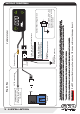
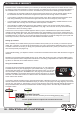
- installation 1/8” I.D. vacuum hose Red wire +12V switched power source Blue wire - External input (see notes below, and pages 12 & 14 for details) Yellow wire - not used, future features (see notes below) Black wire Vehicle ground (chassis) Loom Vacuum hose joiner MENU Remote trigger button (not supplied). Use any switch, button or sensor that grounds the blue wire when activated WARNING! Do NOT connect the blue or yellow wire to a 12V source as this could damage the unit.
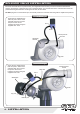
solenoid valve installation Mount the solenoid valve in a position away from significant heat sources (such as the exhaust manifold and turbine), and where it is protected from rain or splashed water. The unused outlet of the solenoid valve should be positioned facing downwards to avoid ingress of dust, dirt and water. DO NOT plug the un-used solenoid port, as this will prevent the controller from being able to adjust boost pressure.
menu structure RUNNING MODE (Normal controller operation) Hold MENU To exit from the menu at any point To enter menu and advance through the options Duty Cycle Display scrolls “dUtY”, followed by “PEAK”. Details see page 7. Gain Display scrolls “gAIn”. For more details, see page 8. Sensitivity Display scrolls “SEnS”. For more details, see page 9. Scramble Seconds Display scrolls “SCr SEC”. For more details, see page 10. Overboost Display scrolls “OVErbSt”. For more details, see page 11.
boost presets The G-Force II has 6 boost presets (P1-6), each of which can be individually programmed and accessed quickly on-the-fly using a variety of different methods. There is an additional preset called “SCr”, which is the preset that is activated when the scramble feature is used. See page 10 for more info on scramble. “SCr” can be set up and used just like any other preset, so effectively there are actually 7 presets in total.
duty cycle BEFORE adjusting duty cycle, it is HIGHLY recommended that you first set up the OVERBOOST feature (see page 11 for more information). STOP OVERBOOST is a “global” setting that will turn off the solenoid if boost pressure exceeds the overboost setting (regardless of the boost preset currently being used), which is intended to prevent damage to your engine if the controller is adjusted incorrectly or accidentally. The factory default setting is 100kPa (1 bar, 14.5psi).
Gain The Gain setting controls how fast boost pressure rises during spool-up. NOTE: the gain setting requires a target “peak” boost to be set up in duty cycle. If you adjust duty cycle without performing a boost run, the target boost will be 0 and gain will not function. Gain is adjustable from 0-100, where 0 gives a factory-like spool up, which is basically the “natural” rise rate of the turbo system.
Sensitivity The Sensitivity setting controls a closed-loop correction factor that attempts to correct any difference between the actual boost and the target boost pressure. This is useful on a turbo that tends to drop boost pressure as RPM rises (boost taper), and can also help pull boost pressure up to the target when it is rising very slowly (such as in a very high gear). NOTE: the sensitivty setting requires a target “peak” boost to be set up in duty cycle.
scramble boost Scramble boost is a feature that allows you to increase (or decrease) boost pressure for a certain amount of time by clicking a remote-mounted button or switch (see page 3 for details on how to wire up a remote button/switch), or the “scramble” button on the G-Force’s screen. This feature may be useful in the following example situations: ? In a drag-race, the controller could be set up with a lower boost pressure in order to maintain traction off the line.
overboost Overboost is a safety feature that will turn off the solenoid and flash the buttons red if the boost pressure exceeds the limit set in this menu option. This will help prevent damage to the engine if an accidental or incorrect adjustment is made to the controller, which is particularly helpful during boost setup. The factory default value for overboost is 100kPa (1bar, or 14.5psi). Overboost is adjustable between 0 - 345 kPa (0 - 3.45 bar, 0 - 50 psi).
display setting - units of pressure Display allows you to configure the boost gauge display to read boost pressure in kPa (default), BAR or PSI. Note that when PSI is selected, vacuum is displayed in inHg (inches mercury), which is the same as found on most psi unit boost gauges.
Colour settings Colour allows you to configure the button colours - both the normal “background” colour (i.e. when not pressed), and also the “feature active” colour, which is the colour a button turns when either scramble or preset features are activated (see pages 6 and 10).
Tips Here are some handy suggestions for different ways you can set up and use the features on your G-Force II. If you set the “INPUT” menu item to “SCr” (scramble), then you can use the external input wire to trigger scramble in a variety of different ways to achieve different outcomes. For example, you can connect the external input wire to: ? Steering wheel button - easy access to use as a “push-to-pass” system.
Troubleshooting Boost pressure remains the same regardless of the duty cycle setting: Turn the ignition off, then on again and listen for the solenoid to click rapidly for about 1 second. If you can’t hear it click on power up, check the wiring loom to the solenoid valve.
Tech Duty Cycle - what the heck is it? Duty cycle refers to how the solenoid valve is actually controlled. The G-Force II boost controller outputs a signal to the solenoid valve that rapidly pulses it on and off about 30 times a second (0.033 seconds per cycle) to bleed air from the wastegate, and duty cycle alters how long it is on for each cycle, and how long it is off. For example, a duty cycle of 25% means that the solenoid valve is pulsed ON for 25% of each cycle, and OFF for 75% of the cycle.