Utility model patent NO. EPSOLAR 201120064092.1 Tracer-4210RN / 4215RN —— Maximum Power Point Tracking Solar Charge Controller INSTRUCTION MANUAL Thank you very much for selecting our product! This manual offers important information and suggestions with respect to installation, use and troubleshooting, etc. Please read this manual carefully before using the product and pay attention to the safety recommendations in it.
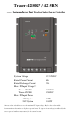
Tracer-4210RN / 4215RN —— Maximum Power Point Tracking Solar Charge Controller System Voltage 12 / 24VDC Rated Charge Current 40A Rated Discharge Current 20A Max. PV Input Voltage** Tracer-4210RN Tracer-4215RN 100VDC 150VDC Max. PV Input Power 12V System 24V System 520W 1040W **Array voltage should never exceed maximum PV input voltage.
Contents 1 Important Safety Information ............................................... 1 2 General Information ............................................................. 2 2.1 Overview.................................................................. 2 2.2 Optional Accessories................................................ 4 3 Installation Instructions ........................................................ 5 3.1 General Installation Notes ........................................ 5 3.2 Mounting.......
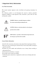
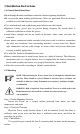
1 Important Safety Information Save These Instructions This manual contains important safety, installation and operating instructions for Tracer. The following symbols are used throughout this manual to indicate potentially dangerous conditions or mark important safety instructions,please take care when meeting these symbols. WARNING: Indicates a potentially dangerous condition. Use extreme caution when performing this task.
2 General Information 2.1 Overview Thank you for selecting the Tracer controller which represents advanced technology of our company. The features are listed below: · 12V / 24V auto recognition. · Advanced maximum power point tracking technology to optimize using the solar system. · Peak conversion efficiency of 97 %, high Tracking efficiency of 99%. · Very fast sweeping of the entire I-V curve, several seconds tracking speed. · Widely used, automatic recognize day/night.
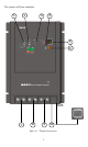
The features of Tracer controller: 2 1 4 3 5 6 RJ45 7 8 9 10 Figure 2-1 Tracer Characteristics 3
1 – Charging Status LED Indicator An LED indicator that shows charging status and overvoltage of battery. 2 – Battery Status LED Indicator An LED indicator that shows battery status or system errors. 3 – Temperature Sensor Measure ambient temperature and make temperature compensation for charging and discharging. 4 – Setting Indicators Corresponding indicator will be on when set timer1, timer2 and battery type. 5 – LED Digital Display Display the load work mode and status.
3 Installation Instructions 3.1 General Installation Notes Read through the entire installation section first before beginning installation. Be very careful when working with batteries. Wear eye protection. Have fresh water available to wash and clean any contact with battery acid. Uses insulated tools and avoid placing metal objects near the batteries. Explosive battery gasses may be present during charging. Be certain there is sufficient ventilation to release the gasses.
Step 4: Drill Holes Remove the controller and drill four sizeable holes in the marked locations. Step 5: Secure Controller Place the controller on the surface and align the mounting holes with the drilled holes in step 4. Secure the controller in place using the mounting screws. 3.3 Wiring NOTE: A recommended connection order has been provided for maximum safety during installation. NOTE: The Tracer is a negative ground controller.
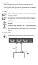
Before connecting the battery, measure the battery voltage. It must be over 9V to power the controller. For 24V, the voltage must be greater than 18V to properly detect a 24V battery. The 12/24V battery detection is automatic and the check is only performed at start-up. Wire an in-line fuse holder no more than 150mm from the battery positive terminal. Do not insert a fuse at this time. Confirm the connection correct and then turn on the power.
The Tracer can accept 12V, 24V nominal off-grid solar module arrays. Grid –tie solar module(s) may be used if the open circuit voltage does not exceed the maximum solar input rating. The solar module(s) nominal voltage must be equal to or greater than the nominal battery voltage. Solar Module Figure3-3 Solar Module wiring Step 4: Accessories (option) Install Remote Meter (purchased separately) if required. Refer to the instructions provided for detailed installation procedures.
4 Operation 4.1 MPPT Technology The Tracer utilizes Maximum Power Point Tracking technology to extract maximum power from the solar module (s). The tracking algorithm is fully automatic and does not require user adjustment, Tracer technology will track the array maximum power point voltage (Vmp) as it varies with weather conditions, ensuring that maximum power is harvested from the array through the course of the day.
Current VS. Voltage in 12V system Typical Battery Voltage Range Figure 4-1 Output power in 12V system Maximum Power Point Traditional Controller Operating Range Tracer Maximum Power Point Nominal 12V Solar Module I-V curve and output power graph The array Vmp is the voltage where the product of current and voltage (Amps×Volts) is greatest, which falls on the ―knee‖ of the solar module I-V curve as shown in Figure4-1.
Figure 4-2 Tracer MPPT charging algorithm · Bulk Charge In this stage, the battery voltage has not yet reached boost voltage and 100% of available solar power is used to recharge the battery. · Boost Charge When the battery has recharged to the Boost voltage setpoint, constant-voltage regulation is used to prevent heating and excessive battery gassing. The Boost stage remains 120 minutes and then goes to Float Charge.
· Equalize WARNING: Risk of explosion! Equalizing flooded battery can produce explosive gases, so well ventilation of battery box is necessary. NOTE: Equipment damage! Equalization may increase battery voltage to the level damaging to sensitive DC loads. Ensure that all load allowable input voltages are greater than the equalizing charging set point voltage. NOTE: Equipment damage! Over-charging and excessive gas precipitation may damage the battery plates and activate material shedding on them.
Charging Indicator The green LED indicator will light whenever sunlight is available for battery charging, the green charging LED will stay on in normal charging. The charging LED indicator flashes when battery over voltage. Please refer to Chapter 5 for troubleshooting.
Load indicator When the load amp is 1.25times of rated current for 60 seconds, or the load amp is 1.5 times of rated current for 5 seconds (overload); or load short circuit, the Battery Indicator RED FLASHING. Please refer to section 5 for troubleshooting.
4.4 Setting Operation Dual Timer Function Timer1 Light ON Timer2 Midnight Light OFF Number Number of hours of hours Sunset Sunrise The default night length is 10 hours.The controller can learn the night length referring to the previous night so as to adapt to the different seasons. However, it will take some time to learn it.
Load Work Mode Setting Timer1 Setting indicator Work mode LED digital tube Timer2 Setting indicator Battery type Setting Indicator Setting button Figure 4-4 Instruction figure on setting Press the setting button once and setting indicators will be changed once among timer 1, timer2 and battery type. When timer 1 setting indicator is on, press the setting button for more than 5 seconds till the LED digital tube flashes.
Load work mode Table 4-5 LED Timer1 Digital No.
Load work mode Table 4-6 Timer2 LED Digital No.
5 Protections, Troubleshooting and Maintenance 5.1 Protection · PV Array Short Circuit If PV array short circuit occurs, clear it to resume normal operation. · PV Overvoltage If PV Overvoltage occurs, the array will remain disconnected until the voltage falls safely below the maximum rating. · Load Overload If the load current exceeds the maximum load current rating, the controller will disconnect the load. Overloading must be cleared up through reapply power or pressing the setting button.
5.2 Troubleshooting Trouble Shooting Table 5-1 Faults Charging LED indicator off during daytime when sunshine falls on PV modules properly. Green charging LED indicator flashing Possible reasons PV array disconnection Troubleshooting Check that PV and battery wire connections are correct and tight. Check if battery voltage over high.
5.3 Maintenance The following inspections and maintenance tasks are recommended at least two times per year for best controller performance. Check that the controller is securely mounted in a clean and dry environment. Check that the air flow and ventilation around the controller is not blocked. Clear all dirt or fragments on the heat sink. Check all the naked wires to make sure insulation is not damaged for serious solarization, frictional wear, dryness, insects or rats etc.
6 Warranty The Tracer charge controller is warranted to be free from defects for a period of TWO (2) years from the date of shipment to the original end user. We will, at its option, repair or replace any such defective products. • Claim procedure: Before requesting warranty service, check the Operation Manual to be certain that there is a problem with the controller. Return the defective product to us with shipping charges prepaid if problem cannot be solved. Provide proof of date and place of purchase.
7 Technical Specifications • Electrical Parameters Description Parameter Nominal System Voltage 12VDC / 24VDC Auto work Rated Charge Current 40A Rated Discharge Current 20A Maximum Battery Voltage 32V Tracer-4210RN 100VDC Tracer-4215RN 150VDC Max. Solar Input Voltage 12V / 520W Max. PV input power 24V / 1040W Self-consumption* <10mA(24V) Charge Circuit Voltage Drop ≤0.26V Discharge Circuit Voltage Drop ≤0.
• Threshold Voltage Description Parameter NTTV (Night Time Threshold Voltage) 5V; x2/24V DTTV (Day Time Threshold Voltage) 6V; x2/24V • Temp compensation Description Temperature Compensation Coefficient(TEMPCO)* Parameter -30mV/℃/12V(25℃ ref) * Compensation of equalize, boost, float and low voltage disconnect voltage.
PV Power — Conversion Efficiency Curve Illumination Intensity: 1000W/m2 Temperature: 25℃ Tracer-4210RN: 1. Solar Module MPP Voltage(17V) / Nominal System Voltage(12V) (η) 97.0% 96.5% 96.0% 95.5% 95.0% 94.5% 94.0% 93.5% 93.0% (W) 520 480 450 420 390 360 330 300 270 240 210 180 150 90 120 Solar Module MPP Voltage(34V) / Nominal System Voltage(12V) (η) 96.5% 96.0% 95.5% 95.0% 94.5% 94.0% 93.5% 93.0% 92.
3. Solar Module MPP Voltage(68V) / Nominal System Voltage(12V) (η) 94.5% 93.5% 92.5% 91.5% 90.5% 89.5% (W) 520 480 450 420 390 360 330 300 270 240 210 180 150 90 120 Solar Module MPP Voltage(34V) / Nominal System Voltage(24V) (η) 98.0% 97.0% 96.0% 95.0% 94.0% 93.0% 92.0% 91.0% (W) 1040 990 930 870 810 750 690 630 570 510 450 390 330 270 210 150 90 90.0% 30 4. 60 30 88.
Solar Module MPP Voltage(68V) / Nominal System Voltage(24V) (η) 100.0% 95.0% 90.0% 85.0% 80.0% (W) 990 1040 930 870 810 750 690 630 570 510 450 390 330 270 210 90 150 75.0% 30 5.
Tracer Dimensions (mm)
BEIJING EPSOLAR TECHNOLOGY CO., LTD. Tel:010-82894112 / 82894962 Fax:010-82894882 E-mail:info@epsolarpv.com Website:www.epsolarpv.