
Installation and Operation Guide

EN
17
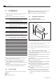
Installation
www.bora.com
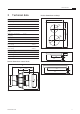
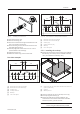
5.4.1 Flush installation
x
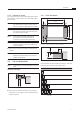
A ±2
B ±2
544 ±2
≤ R5
≤ R5
≥ 74
≥ 74
516 ±2
≥ 700
Fig. 5.3 Cut-out dimensions ush installation
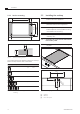
7 +0,5
14
10 - 40
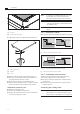
Fig. 5.4 Groove dimensions for ush installation
Cut-out dimensions when installing cooktops or cooktops
and the cooktop extractor next to each other:
Cooktops/cooktop extractor A in mm B in mm
1/0 374 346
1/1 485 457
2/1 856 828
3/2 1338 1310
4/2 1709 1681
Tab. 5.2 Cut-out dimensions appliance combinations ush
installation
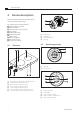
5.3.3 Cooktop air intake
The components in the cooktop which generate heat are
automatically cooled. The warm air is extracted by fans
(cold air flow).
INFO In order to retain the full functionality of
the cooktop in the long term, there must be
sufficient ventilation underneath the cooktop.
INFO The performance of the cooktop is impaired or
the cooktop overheats if the warm air below
the cooktop cannot escape.
INFO If the cooktop overheats, performance
is reduced or the cooktop switches off
completely (see Overheating protection).
INFO For sufficient air intake, an opening cross-
section in the kitchen units of at least 50 cm
2
is recommended.
Ensure there is sufficient ventilation underneath the
cooktop.
INFO If there are plans for a cable protection floor
(false floor) below the device, this must not
impede the ventilation.
5.4 Cut-out dimensions
INFO All dimensions from the front edge of the front
cover.
Worktop overhang
≥ 74x
Fig. 5.2 Worktop overhang
Please note the worktop overhang x when creating
the worktop cut-out. Applies to flush installation and
surface mounting.