
Installation and Operation Guide

EN
19
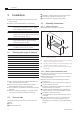
Installation
www.bora.com
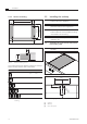
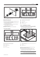
≥70
90 90 909090 196 196 196 196
370 370
370
110
1 1 1 1
110
Ø50 ±0,5
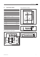
Fig. 5.11 Bore holes for 3 cooktops and 2 extractors
[1] Bore holes for socket (2x external)
[2] Bore holes for control knobs (8x)
[3] Cooktop (3x)
[4] Cooktop extractor (2x)
[5] Worktop
[6] Floor unit’s panel
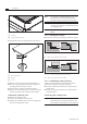
5.5.2 Installing the cooktop
Please note the position of the cooking zone indicator.
Alternatively, the cooktop can be installed rotated by
180° (see Installation rotated by 180°).
321
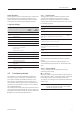
Fig. 5.12 Inserting the cooktop
[1] Connections for the control knob and automatic extraction
system (at the front)
[2] Cooktop
[3] Worktop cut-out
Insert the cooktop [2] into the worktop cut-out [3].
Precisely align the cooktop [2].
Please note that during normal installation, the
connections for the control knob and the automatic
extraction system [1] are at the front.
INFO The device connector should be fed backwards.
Do this using the cable brackets provided.
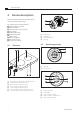
Fig. 5.9 Installing the control knob
Pull off the selector ring.
Unscrew the fixing nut.
Push the control knob through the drilled hole in the
floor unit’s panel from the front.
Screw the fixing nut onto the control knob from the
back and lightly tighten it.
Vertically align the control knob in the 12 o’clock
position based on the markings.
Tighten the fixing nut.
Place the selector ring on the control knob.
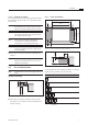
Bore hole examples
≥70
90 90 90
Ø50 ±0,5
90 196 196
370 370
110
1 1
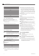
Fig. 5.10 Bore holes for 2 cooktops and 1 extractor
[1] Bore holes for socket (2x external)
[2] Bore holes for control knobs (5x)
[3] Cooktop (2x)
[4] Cooktop extractor
[5] Worktop
[6] Floor unit’s panel