
Installation and Operation Guide

EN
22
Installation
www.bora.com
Connecting the cooking zones when the cooktop is
installed rotated by 180°
5 4
3
2
1
7
6
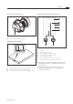
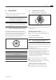
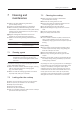
Fig. 5.20 Connecting the cooking zones with 180° installation
[1] Cooktop
[2] Rear cooking zone (zone 1)
[3] Front cooking zone (zone 2)
[4] Control knob for the rear cooking zone (zone 1)
[5] Control knob for the front cooking zone (zone 2)
[6] Front cooking zone indicator (zone 2)
[7] Rear cooking zone indicator (zone 1)
Connect the connection on the back of the left control
knob [5] with the ‘zone 2’ connection on the back of
the cooktop [1].
Connect the connection on the back of the right
control knob [4] with the ‘zone 1’ connection on the
back of the cooktop [1].
Use the configuration menu to correctly set the
assignment of the cooking zones in the control knob
display (see Configuration menu, installation 0° or
180°).
Connecting the automatic extraction system
Connect the cooktop extractor to the connection
provided for the automatic extractor system on the
cooktop.
5.5.5 Establishing the power connection
Observe all safety and warning information (see the
Safety section).
Observe all national and regional laws and regulations
as well as the supplementary regulations of the local
utility companies.
INFO The power connection may only be established
by certified specialists. The specialist
also assumes responsibility for the proper
installation and commissioning.
The power supply line to be used (pre-assembled) must
be at least type H05VV-F or H05VVH2-F (see the Fuse
protection and minimum cross-section table).
Connection Fuse protection Minimum
cross-section
1-phase connection 1 x 16 A 1.5 mm
2
Tab. 5.4 Fuse protection and minimum cross-section
If the connection cable has been damaged, it must
be replaced. This may only be done by an authorized
member of the After Sales Service team.
Switch off the main switch/automatic circuit breaker
before connecting the cooktop.
Secure the main switch/automatic circuit breaker
against being switched back on without permission.
Make sure the power to the appliance is disconnected.
Only connect the cooktop using a permanent
connection to a power supply cable.
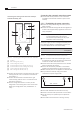
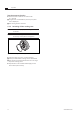
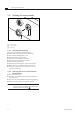
1
L1
2
N PE
220 - 240 V~
Fig. 5.21 Connection diagram 1-phase
Check that installation has been done correctly.
Switch on the main switch/automatic circuit breaker.
Put the cooktop into operation (see the Operation
section).
Check that all the functions are working correctly.