
Installation Guide


3
VERSETTA STONE
®
MANUFACTURER’S INSTALLATION INSTRUCTIONS
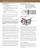
Wall Layout
Marking Framing Locations
Mark vertical framing locations with pencil or chalk line.
It may also be helpful to mark horizontal framing locations
in areas around windows, doors and wall terminations.
Verify that your intended starting line provides an equal
height distance to overhang, trim or cladding. Once a
starting location has been determined, tack or tape up
WRB and mark on sheathing. Account for Starter Strip
nailing flange, so that bottom of Starter Strip lands on your
desired starting location. Extend a chalk line or pencil line
across the entire surface to be covered.
Markings to Stay Level
Panels are designed to help maintain level and plumb
courses but it is also advised that you mark level lines
periodically up the wall as a reference. A level line every 24"
is recommended. This allows you to quickly measure to the
line to verify panels are still running level. Adjusting panel
spacing to catch up distance or level can be done, but this
must be done in 1⁄16" or less increments.
INSTALLATION
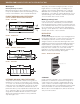
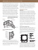
Starter Strip
Install Starter Strip perfectly level at your starting point line.
Fasten with roofing nails or screws every 8"-10". Fasteners
should be placed in the center of nail slots and driven
straight. Fasteners should not be driven tight. Allow 1⁄32"
gap between fastener head and strip. Additional fasteners
may be added to assure strip does not easily pull away
from wall at bottom edge. Allow ¼" clearance at material
butt joints and ½" clearance at corners and end wall
terminations to allow for proper alignment of panels. Lap
WRB over starter strip nail flange. See Figure 9.
J Channel
Install J Channel at windows, doors, material transitions,
penetrations or terminations. Fasten with roofing nails or
screws every 8"-10". Fasteners should be placed in the
center of nail slots and driven straight. Fasteners should
not be driven tight. Allow 1⁄32" gap between fastener head
and channel. Allow ¼" clearance at material butt joints.
When used in horizontal applications, drill 3⁄8" drain holes
every 12" in trim channel.
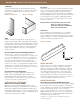
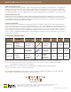
FIGURE 5 - FLAT PANEL
9.5
8.0
FIGURE 7 - UNIVERSAL CORNER (UN-CUT)
FIGURE 8 - TRIM PANEL
FIGURE 6 - WAINSCOT CAP
2.2
3
PRODUCT DIMENSIONS AND SPECIFICATIONS
(SUBJECT TO NORMAL MANUFACTURING TOLERANCES)
FIGURE 9 - WATER RESISTIVE BARRIER
water-resistive barrier
DETERMINE AND MARK YOUR STARTING POINT
The product must maintain a clearance from grade of a
minimum 4" if soil and 2" if a hard surface such as paving
or concrete. It is critical that your starting line be a level line
and positioned so that appropriate clearance from grade
is achieved. This location will also determine the size of
partial units when you reach penetrations like windows and
doors. Take time to plan a location that optimizes panel
usage above and below windows and doors. Product
dimensions have been provided to assist you with this
step. See Figures 5–8.