gas barbecue NL BE FR BE ES GB Montage-instructies Instructions d’assemblage Instrucciones de armado Assembly instructions Modulo Professional
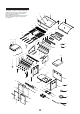
PARTS LIST Ref 1 1a 2 3 4 5 6 7a 7b 8 9 10 11 12 13 14 15 16 17 18 19 19a 19b 19c 19d 20 21 22 23 24 25 26 27 28 29 30 31 32 Description Hood assembly Hood trim plate Protective pad Temperature gauge Hood badge Hood handle Cooking rack – fixed Grill plate Hot plate Flame tamer Body panel – left Body panel – right Body panel – front Body panel – rear Body panel – rear wind shield Burner – main Burner support bracket Gas collector box with electrode Electric wire set Electric igniter – 4 port Gas valve / ma
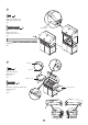
PARTS DIAGRAM This diagram is provided to assist you identify parts if replacement is necessary. Contact your place of purchase or the manufacturer to enquire about parts, availability and or service.
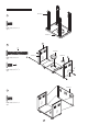
ASSEMBLY Ref # 59 1 Phillips-head screw 1/4" x 1/2" Qty. 16 Ref # 33 L 2 A Ref # 60 Phillips-head screw Qty. 8 1/4" x 2" A Ref # 61 Ref # 37 R B B Phillips-head screw 1/4" x 1/2" Qty. 2 Ref # 38 Ref # 41 3 Phillips-head screw 1/4" x 1/2" Qty.
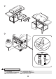
4 Phillips-head screw 1/4" x 2" Qty. 4 Ref # 42 5 Ref # 51 A Ref # 52 Door handles Phillips-head screw 1/4" x 21/4" Qty. 4 A B Door hinges, guide plate Phillips-head screw 3/16" x 3/8" Qty.
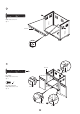
A Lighting stick to barbecue body Phillips-head screw M4 x 8 mm Qty. 1 B B Lighting Stick Barbecue head to trolley Phillips-head screw 1/4" x 13/16" Qty. 4 B Lighting stick Qty. 1 7 Ref # 31 A B Ref # 32 Tool holder to side shelf Phillips-head screw M5 x 8 mm Qty. 2 Ref # 29 / 29a B Side shelves / side burner to barbecue head Phillips-head screw 1/4" x 3/4" Qty.
8 Ref # 26 Ref # 27 Ref # 28 9 Ref # 34 Ref # 39 WARNINGS INFORMATION NL FR DE VENTILATIEOPENINGEN IN DE TROLLEY NIET BLOKKEREN. NE PAS BOUCHER LES OUVERTURES DE VENTILATION DANS LE CHARIOT. ES GB NO OBSTRUYA LAS ABERTURAS DE VENTILACIÓN DEL CARRITO. DO NOT OBSTRUCT THE VENTILATION OPENINGS IN THE TROLLEY.
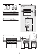
IGNITION BATTERY LIGHT BBQ WITH MATCH AA battery Lighting hole Igniter cap Contact Spring Match Lighting stick COOKING COMPONENT INSTALLATION Secondary cooking / warming rack Ref # 6 Grill plate TEMPERATURE GAUGE Flame tamer Ref # 7b Ref # 7a Ref # 8 Slots for Secondary cooking / warming rack 8
INJECTOR WARNINGS INFORMATION • MINIMUM CLEARANCES FROM COMBUSTIBLE MATERIALS MUST BE: REAR - 450 mm SIDES - 250 mm TOP - 1000 mm Main Main Rotisserie Rotisserie 1.00 mm – I 3+ (28-30/37) – I 3B/P (30) 0.90 mm – I 3B/P (50) 1.00 mm – I 3+ (28-30/37) – I 3B/P (30) 0.90 mm – I 3B/P (50) 250 mm INPUT 22.0 kW – 1598 grams / h 4.
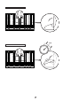
COOKING WITH HOOD OPEN 250˚ COOKING WITH HOOD DOWN 10
www.boretti.com BORETTI b.v. De Dollard 17 1454 AT Watergang T +31(0)20-4363439 F +31(0)20-4361326 E info@boretti.com The Netherlands n.v. BORETTI s.a. Rupelweg 16 2850 BOOM T +32-(0)3-4508180 F +32-(0)3-4586847 E info@boretti.com Belgium BORETTI s.l. Oficina en Avd. de la Barrosa 63c 11139 Chiclana de la Frontera (Cadiz) T +34 956 494684 F +34 956 494150 E info@boretti.com Spain NL BE ATTENTIE: Deze informatie is alleen bedoeld als gids.