
Installation Guide


All information is subject to change without notice Page 9 of 12
Borroughs Document Number: DOC-MDC-0011 Rev. 2.0
www.borroughs.com 1-800-748-0227
End Guards
STEPS
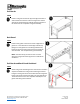
Position end guard so that two (2) holes align with holes in
side of attachment channel. Fasten end guard to channel
with two (2) 07792-00 and 17213-00. Repeat procedure at
the other end. This completes end guard assembly.
Back Guard
STEPS
Position back guard so that ovals in lower edge of back
guard are in line with holes in back edge of bench top.
(Flanges on back guard are to be facing toward front).
Fasten back guard to bench top with five (5) 07792-00
and 17213-00. This completes back guard assembly
NOTE: The extra two (2) screws and nuts are used
when the end guards and back guard are combined on
workbench.
End Guards and Back Guard Combined
STEPS
Attach end guards and back guard to work bench as stated in
separate assemblies for end guards and back guard above.
Flanges on back guard are to be located inside of end guards.
Fasten end guards to back guard with one (1) 07792-00 and
17213-00 at each corner. This completes assembly for end
guards and back guard combined.