Video Recorder 430/451 Series Four Channel Digital Video Recorder en Installation and Operation manual
Video Recorder 430/451 Series Table of Contents | en 3 Table of Contents 1 Safety 7 1.1 Safety precautions 7 1.2 Important safety instructions 7 1.3 Important Notices 9 1.4 FCC and UL 11 1.5 Bosch notices 12 2 Introduction 13 2.1 Digital video recorder applications 13 2.1.1 Versions 13 2.1.2 Manuals 13 2.1.3 Features 14 2.2 Unpacking 14 2.2.1 Package contents 14 2.3 Installation environment 15 2.3.1 Mounting 15 2.3.2 Ventilation 15 2.3.
en | Table of Contents Video Recorder 430/451 Series 4.10 Maintenance 26 5 Operating instructions 27 5.1 Front panel controls 27 5.1.1 Keys 28 5.1.2 Indicators 29 5.2 Mouse Controls 30 5.3 Remote control 31 5.4 Viewing pictures 32 5.4.1 Monitor A 32 5.4.2 Monitor B 32 5.4.3 Viewing 32 5.5 Live and playback 34 5.5.1 Live mode 34 5.5.2 Playback mode 34 5.6 Overview of the menu system 35 5.6.1 Access using the front panel keys 35 5.6.
Video Recorder 430/451 Series Table of Contents | en 5 6.4.1 Input 57 6.4.2 Motion 58 6.4.3 Alarm acknowledge 59 6.4.4 System menu 60 6.5 Network 61 6.5.1 TCP/IP 61 6.5.2 Streaming to mobile devices 61 6.5.3 Connecting using a smart mobile phone 61 6.5.4 DDNS 63 6.5.5 Notification 63 6.5.6 Mail 64 6.6 System 65 6.6.1 Date/Time 65 6.6.2 NTP 65 6.6.3 Beeper 65 6.6.4 Users 66 6.6.5 Configuration 67 6.6.6 Hard Disk 68 6.6.
en | Table of Contents Video Recorder 430/451 Series 8.9 Exit button 80 9 Menu default values 81 10 Technical specifications 85 10.1 Electrical 85 10.1.1 Mechanical 86 10.1.2 Environmental 86 10.1.3 Electromagnetic and Safety 87 10.2 DVD compatibility 87 10.3 USB memory sticks 87 A Appendix 88 A.1 Software licenses 88 A.1.1 Bosch software 88 A.1.2 Other licenses — copyright notices 88 A.1.3 Warranties and disclaimer of warranties 89 F.01U.168.054 | v2.0 | 2012.
Video Recorder 430/451 Series Safety | en 1 Safety 1.1 Safety precautions 7 DANGER! High risk: This symbol indicates an imminently hazardous situation such as "Dangerous Voltage" inside the product. If not avoided, this will result in an electrical shock, serious bodily injury, or death. WARNING! Medium risk: Indicates a potentially hazardous situation. If not avoided, this could result in minor or moderate bodily injury. CAUTION! Low risk: Indicates a potentially hazardous situation.
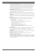
en | Safety Video Recorder 430/451 Series 9. Power supply cord and plug protection - Protect the power supply cord and plug from foot traffic, being pinched by items placed upon or against them at electrical outlets, and its exit from the unit. For units intended to operate with 230 VAC, 50 Hz, the power supply cord must comply with the latest versions of IEC 60227. For units intended to operate with 120 VAC, 60 Hz, the power supply cord must comply with the latest versions of UL 62 and CSA 22.2 No.
Video Recorder 430/451 Series 1.3 Safety | en 9 Important Notices Accessories - Do not place this unit on an unstable stand, tripod, bracket, or mount. The unit may fall, causing serious injury and/or serious damage to the unit. Use only with the cart, stand, tripod, bracket, or table specified by the manufacturer. When a cart is used, use caution and care when moving the cart/apparatus combination to avoid injury from tip-over.
en | Safety Video Recorder 430/451 Series Environmental statement - Bosch has a strong commitment towards the environment. This unit has been designed to respect the environment as much as possible. Fuse rating - For protection of the device, the branch circuit protection must be secured with a maximum fuse rating of 16A. This must be in accordance with NEC800 (CEC Section 60).
Video Recorder 430/451 Series 1.4 Safety | en 11 FCC and UL FCC Information (U.S.A. and Canadian Models Only) This equipment has been tested and found to comply with the limits for a Class B digital device, pursuant to part 15 of the FCC Rules. These limits are designed to provide reasonable protection against harmful interference in a residential installation.
1.5 en | Safety Video Recorder 430/451 Series Bosch notices Copyright This manual is the intellectual property of Bosch Security Systems and is protected by copyright. All rights reserved. Trademarks All hardware and software product names used in this document are likely to be registered trademarks and must be treated accordingly. Note: This manual has been compiled with great care and the information it contains has been thoroughly verified.
Video Recorder 430/451 Series Introduction | en 2 Introduction 2.1 Digital video recorder applications 13 The Digital Video Recorder 430/451 Series is a video and audio recording system that records multiple camera and audio signals while simultaneously providing live multiscreen viewing and playback. The unit has comprehensive search and playback facilities for viewing stored video. Once configured, all recording takes place in the background without requiring operator intervention.
en | Introduction 2.1.3 Video Recorder 430/451 Series Features The DVR 430/451 Series has the following features: – 4 looped-through, auto-terminating camera inputs – 1 or 4 audio inputs – Simultaneous recording and playback – H.264 compression – 10/100Base-T Ethernet port for Ethernet connection and networking – RS232 and RS485 serial port for serial communication – VGA monitor output (Monitor A) – – – 2.
Video Recorder 430/451 Series Introduction | en 2.3 Installation environment 2.3.1 Mounting 15 The DVR 430/451 Series is supplied as a desktop unit. 2.3.2 Ventilation Ensure that the location planned for the installation of the unit is well ventilated. Take note of the locations of the cooling vents in the unit's enclosure and ensure that they are not obstructed. 2.3.3 Temperature Observe the unit's ambient temperature specifications when choosing an installation space.
en | Quick install 3 Video Recorder 430/451 Series Quick install To get the unit quickly operational, make the connections described below and then enter the relevant data in the Quick install menu. The Quick install menu appears the first time the unit is started. 3.1 Connections Figure 3.1 Back panel connections for the Advanced model Figure 3.2 Back panel connections for the Basic model 3.1.1 Primary connections 1.
Video Recorder 430/451 Series 3.2 Quick install | en 17 First-time use The Quick install menu opens the first time the unit is used. Fill in the basic settings in the three tabs to get the unit operational. The unit begins recording automatically when the Quick install menu is closed. To open the Quick install menu at any other time: 1. Press the menu key to bring up the System Control Bar. 2. Press the menu key again to enter the main menu. – The main menu appears on monitor A. 3.
en | Quick install 3.3 Video Recorder 430/451 Series Quick install menu The Quick install menu contains three tabs: International, Continuous Recording, and Network. Click the Exit button to exit the Quick install menu. Changing Quick install settings overwrites customized settings. 3.3.1 International Figure 3.3 Quick install - International Language Select the language for the menu from the list. Time zone Select a time zone from the list.
Video Recorder 430/451 Series 3.3.2 Quick install | en 19 Continuous Recording Figure 3.4 Quick install - Continuous Recording Set the Continuous Recording Resolution, Quality, Frame rate, Covert, and Audio for each profile in the table. Bosch Security Systems Installation and Operation manual F.01U.168.054 | v2.0 | 2012.
en | Quick install 3.3.3 Video Recorder 430/451 Series Network Figure 3.5 Quick install - Network Fill in the settings that control the behavior of the unit with respect to a network. DVR name Enter a unique DVR name to be used in the network. DHCP Enable DHCP to have IP address, subnet mask, and default gateway assigned automatically by the network server. The actual values are displayed.
Video Recorder 430/451 Series 4 Hardware setup | en 21 Hardware setup This chapter contains detailed information about the hardware installation and connection of external equipment to the unit. The connector types and their pin signals are described. Most of the connectors are located at the rear panel of the unit. For convenience, one USB port is located on the front of the unit to connect a mouse or memory device. All the input/output ports are Safety Extra Low Voltage (SELV) circuits.
en | Hardware setup Video Recorder 430/451 Series Figure 4.3 Audio output and input connectors for the Basic Recorder 4.3 Monitor connections Up to two monitors can be connected through the VGA and CVBS connections. 4.3.1 VGA (Monitor A) Connect the unit to one VGA monitor using standard VGA cable. It is advised to use 17” monitors or larger when using LCD(s). Specifications Output signal: VGA Resolution: 800x600, 1024x768, or 1280x1024 Color: True color (32 bit) Connector type: DE-15 Figure 4.
Video Recorder 430/451 Series 4.4 Hardware setup | en 23 RS-232 COM port connections The RS-232 COM port is used to connect a PC to the unit for service purposes or to connect a Bosch “RS-232 to Bi-Phase Converter”. For service purposes, use a null-modem cable to connect the serial port of the PC to the unit. The Baud rate can be selected in the menu system.
4.5 en | Hardware setup Video Recorder 430/451 Series Ethernet connection The standard RJ-45 Ethernet socket is used to connect the unit directly to a PC or to a network. To connect directly to a network hub, use a straight-through network cable. To connect directly to a PC, use a cross-over network cable. Consult with your local IT personnel for the specific type of cable needed. The maximum cable length from node to node is limited to 100 meters (300 feet).
Video Recorder 430/451 Series Hardware setup | en 25 The recommended cable cross section is AWG 28-16 (0.08-1.5 mm2). 4.7 USB connectors A USB 1.1 connector is located at the rear panel of the unit for use with the mouse. For convenience, the USB 2.0 port is located on the front of the unit to connect a mouse or USB memory device. Figure 4.9 USB mouse port 4.8 External alarm I/O connection Alarm inputs and outputs are supplied screw down terminal blocks.
en | Hardware setup Video Recorder 430/451 Series Figure 4.12 4.9 Alarm output connector for the Basic Recorder Power supply Power is supplied to the unit via the IEC-style socket. For operational reasons, the unit has no on/off switch . This means that the unit is always powered as long as the power cable from the unit is connected to a live power socket. Specifications: Input Voltage: 120-230 VAC Current: 0.5 A AC Input Frequency: 50/60 Hz Figure 4.
Video Recorder 430/451 Series 5 Operating instructions | en 27 Operating instructions These instructions explain the purpose of the front panel keys. The functions available can be limited by setting passwords. Access to the units functions are determined by the user level of the user logged in.
en | Operating instructions 5.1.1 Video Recorder 430/451 Series Keys The keys on the front panel control all functions. Symbols on the keys show the functions. Inactive keys emit an audible beep when pressed.
Video Recorder 430/451 Series Operating instructions | en 29 Digital zoom key – zooms in on the active full screen camera display OSD key – press to view date/time and camera information, date/time only, or none Pause key – press to freeze the picture Reverse key – in live mode, press to start reverse playback of recordings for the displayed cameras – in playback mode, press to start or speed up reverse playback – in pause mode, press to step back one frame Play key – in live mode, press to
5.2 en | Operating instructions Video Recorder 430/451 Series Mouse Controls All functions controlled by the front panel can, alternatively, be accessed using the supplied USB mouse. All main DVR functions are accessible via the System Control Bar. To display the panel (monitor A only), move the mouse pointer to the bottom left of the screen or press the menu key. To close the System Control Bar press the exit key. Figure 5.
Video Recorder 430/451 Series 5.3 Operating instructions | en 31 Remote control All functions controlled by the front panel and USB mouse can, alternatively, be accessed using the supplied remote control. IR remote control allows control of up to nine units without interfering with one another. An ID number must be set on the remote control and in the system. See Section 6.6.7 System for setting the system. To set the ID on the remote control: 1. Press the ID button on the remote control. 2.
en | Operating instructions 5.4 Video Recorder 430/451 Series Viewing pictures The unit has two monitor outputs, A and B. The way in which these monitors display pictures depends on how the system is configured. 5.4.1 Monitor A Monitor A is the main monitor. It shows full-screen or quad multiscreen live, or playback camera pictures. Status messages, alarms, motion, and video loss warnings are also displayed on this monitor. When the menu system is activated, it is displayed on this monitor.
Video Recorder 430/451 Series Operating instructions | en 33 Full-screen To view a full-screen shot of a camera: – Press a camera key. – A full-screen shot of the analog camera that was selected appears. Sequence To view a sequence of live camera pictures of several cameras: 1. Press the sequence – 2. key. A sequence of camera pictures appears, each for a pre-programmed dwell time. Press the sequence – key to stop sequencing.
en | Operating instructions Video Recorder 430/451 Series 5.5 Live and playback 5.5.1 Live mode The live mode is the normal operating mode of the unit where live pictures are viewed from the cameras. From live mode, switch to playback mode or the system menu. 5.5.2 Playback mode Access to playback functions requires the right user level. Discuss this with your administrator. To enter playback mode: 1.
Video Recorder 430/451 Series 5.6 Operating instructions | en 35 Overview of the menu system The Main menu gives access to several functions to help use the unit. Access to the Main menu is only possible with a User Account at the Administrator User Level. There are three ways of accessing the Main menu: – via the front panel keys, – a USB mouse, – via the remote control. Slight differences in navigation and selection are only due to the differences between the keys on the unit and the mouse.
en | Operating instructions 5.6.3 Video Recorder 430/451 Series Main menu Camera The Camera menu is used to configure recording settings for the unit.
Video Recorder 430/451 Series – Operating instructions | en 37 Configuration - Import and Export configuration, reset to Factory defaults, Update firmware and Quick install – Hard Disk - set Overwrite, Disk full warning, Event partition, Auto delete, and format the disk – 5.7 System - set the IR remote control, DVR name, and Auto user logout time Search To Search, press the search key. To Search using the mouse: 1. 2. Move the cursor to the bottom of the screen to access the System Control Bar.
en | Operating instructions 5.7.1 Video Recorder 430/451 Series Date/time search Select the start date. Once the start date has been selected, the timeline will update to show the full 24 hour period. 1. 2. 3. Use the Zoom In button to magnify the timeline. Enter the start time: – Enter the hour and minute. – With a mouse, click directly on the timeline to set the start time. Click Play to start playback: – Playback in all displayed cameos will start. Figure 5.
Video Recorder 430/451 Series 5.7.2 Operating instructions | en 39 Event search 1. From a Date/Time search, press the exit 2. Press the left/right arrow keys to select Event Search. 3. Press the enter – key to select the Search Tabs. key to activate the search. With the mouse, click the Event Search tab to make it active. Search criteria – Under Start and End, fill in date and time values to determine the time span of the search. – – Under Channel, specify the camera input to search for.
en | Operating instructions 5.7.3 Video Recorder 430/451 Series Smart search 1. From a Date/Time search, press the exit 2. Press the left/right arrow keys to select Smart Search. 3. Press the enter – key to select the Search Tabs. key to activate the search. With the mouse, click the Smart Search tab to make it active. Search criteria – – Under Channel, specify the camera input to search for. The selected input will be shown.
Video Recorder 430/451 Series 5.8 Operating instructions | en 41 Export The export menu is accessed by pressing the Export key on the Front Panel or from the System Control Bar. It allows writing segments of recorded video and audio to a USB storage device or recordable DVD. Figure 5.10 Export menu 1. Choose to record to either USB or CD/DVD from the Target Device selection box. 2. Select the Channel to archive. 3. Fill in a Start time and End time for the video segments to archive. 4.
5.9 en | Operating instructions Video Recorder 430/451 Series System information The System information screen is accessed from the System Control Bar by pressing the System Information – Model Name – Serial Number – Video Format – MAC Address icon. The System information menu contains: – IP Address – Software Version – Hard Drive size and usage data Figure 5.11 F.01U.168.054 | v2.0 | 2012.
Video Recorder 430/451 Series 5.10 Operating instructions | en 43 Log The Log displays historic system events and is accessed from the System Control Bar by pressing the Log icon. Logbook filter From the Log display, make a selection of which system events to show. – The Log shows the date, time, and event type of various system events. – Log contents are ordered from latest to earliest. Figure 5.12 Bosch Security Systems Logbook - Logbook filter Installation and Operation manual F.01U.168.
en | Operating instructions 5.11 Video Recorder 430/451 Series Triggers and alarms Various types of events change the way the unit works. These events are: – an alarm input signal applied to the unit – motion detection in a camera signal – a loss of video from one of the cameras – an internal alert from the unit itself (i.e. disk failure, temperature alarm) The way the unit reacts to events depends on how it is programmed. An event can cause either a trigger or an alarm.
Video Recorder 430/451 Series Operating instructions | en 45 Acknowledging an input alarm Press the acknowledge – key to acknowledge the alarm. The beeper is silent. – The alarm – The alarm status message disappears. indicators are no longer lit. – The last-used view mode is restored. The alarm icon remains visible as long as the input causing the alarm is active. If an alarm is not acknowledged, the beeper switches off after the dwell time but the alarm still needs to be acknowledged.
6 en | Configuration menu Video Recorder 430/451 Series Configuration menu Access all the parameters that are used to configure the unit via the menu system. The large number of available parameters gives the opportunity to program extensive functionality. Administrator rights are required to access the configuration menus. There are four ways to access the menu system: – the front panel keys, – a USB mouse, – the IR Remote Control, – remotely via the Web-based Configuration application.
Video Recorder 430/451 Series Top tabs Camera Configuration menu | en 47 Submenus Camera Video Adjustment PTZ Continuous Recording Input Recording Motion Recording Network Live Streaming Schedule Video Format Sunday Monday Tuesday Wednesday Thursday Friday Saturday Display Exception Days Language Monitor A Event Monitor B Input Motion Alarm Acknowledge Network System TCP/IP DDNS Notification System Mail Date/Time NTP Beeper User Configuration Hard Disk System Table 6.
en | Configuration menu 6.1 Video Recorder 430/451 Series Camera Use the Camera menu to configure the recording set up for each of the three profiles. 1. 2. 6.1.1 Configure the settings for Continuous, Input, and Motion recording. – Continuous recording - the default recording mode – Input recording - activated upon an input contact event – Motion recording - activated upon a motion event Choose an input channel to configure the settings for an individual video and audio input.
Video Recorder 430/451 Series Channels Enabled 4 3 2 1 Configuration menu | en CIF 25/30 25/30 25/30 25/30 2CIF 12.5/15 12.5/15 25/30 25/30 49 4CIF 6.25/7.5 6.25/7.5 12.5/15 25/30 Table 6.2 Maximum Frame Rates (PAL/NTSC IPS) by Resolutions for enabled Channels 6.1.2 Video adjustment Figure 6.3 Camera - Video adjustment Channel Select the camera channel for adjustment. The preview will display the channel indicated. Bosch Security Systems Installation and Operation manual F.01U.168.054 | v2.
en | Configuration menu 6.1.3 Video Recorder 430/451 Series PTZ Figure 6.4 Camera - PTZ Select a COM Port, Control ID, and Protocol for PTZ when a controllable camera is connected. – Pan and Tilt can be tested within the menu. – By default, PTZ is disabled for all inputs. F.01U.168.054 | v2.0 | 2012.
Video Recorder 430/451 Series 6.1.4 Configuration menu | en 51 Continuous Recording Figure 6.5 Camera - Continuous Recording Continuous recording mode: – Resolution - set the video resolution to 4CIF (704x576/480 PAL/NTSC), 2CIF (704x288/ 240 PAL/NTSC), or CIF (352x288/240 PAL/NTSC). – Quality - set the video quality setting to Best, High, Normal, Low, or Lowest. – Frame rate - set the video frame rate to 25/30, 12.5/15, 6.25/7.5, 5/6, 2.5/3, or 1/1 IPS (Images Per Second in PAL/NTSC).
en | Configuration menu 6.1.5 Video Recorder 430/451 Series Input Recording Figure 6.6 Camera - Input Recording Use the same procedure as in Continuous Recording. Pre-event Pre-event recording can be switched off or to a displayed pre-event recording time by input and motion recording. The pre-event recording time is dependent on video complexity, resolution, quality, and frame rate settings.
Video Recorder 430/451 Series 6.1.6 Configuration menu | en 53 Motion Recording Figure 6.7 Camera - Motion Recording Use the same procedure as in Input Recording. 6.1.7 Network Live Streaming Figure 6.8 Camera - Network Live Streaming Use the same procedure as Continuous Recording to set the values for cameras that will be streamed over the network. – Bosch Security Systems Network Streams are not recorded. Installation and Operation manual F.01U.168.054 | v2.0 | 2012.
en | Configuration menu – Video Recorder 430/451 Series Network Streaming performance is limited by the total bandwidth between the unit and the PC running the Web-based control application. Note: Disabling channels will allow increasing the frame rate on the remaining enabled channels. Channels Enabled 4 3 2 1 Table 6.3 6.1.8 CIF 12.5/15 12.5/15 25/30 25/30 Maximum Frame Rates (PAL/NTSC IPS) by Resolutions for enabled Channels Video format Figure 6.
Video Recorder 430/451 Series 6.2 Configuration menu | en 55 Schedule Setting the dynamic characteristics The settings in the Schedule menu provide the opportunity to tap the powerful functionality of the unit. By spending some time in planning and setting up the schedules, efficient use of resources is achieved while effectively covering most types of working situations. Recording is scheduled in a weekly calendar, changing the behavior at a particular date or time (for example, weekends or nights).
en | Configuration menu 3. Video Recorder 430/451 Series When finished, select Exit to save the updated schedule. Exception days – Up to 32 exceptions can be set that override the schedule. – To add an exception, select Add. Choose the date from the Calendar. – To edit an exception, select List and then select the value to edit. – To remove an exception, select List and click the Delete button. 6.3 Display 6.3.1 Language – 6.3.2 Select a Language from the list. Monitor A Figure 6.
Video Recorder 430/451 Series 6.4 Configuration menu | en 57 Event Use the Event menu to specify the desired behavior for an Input, detected Motion, or System failures; also define how alarms are acknowledged. 6.4.1 Input Figure 6.12 Event - Input Inputs are always active on the unit. Input Type The Event behavior can be configured independantly for each channel. – N.O. - Normally Open causes an alarm to tigger only when the circuit closes – N.C.
en | Configuration menu 6.4.2 Video Recorder 430/451 Series Motion The motion detection feature can be configured by selecting the camera channel for each individual video input. Figure 6.13 Event - Motion 1. Adjust the Sensitivity to set the theshold at which Motion is detected. 2. Select the Relay Output to trigger in the event of Motion. 3. To define the motion sensitive area in the Area preview cameo window: – Draw in the preview cameo and press Enter to select a motion area.
Video Recorder 430/451 Series 6.4.3 Configuration menu | en 59 Alarm acknowledge The alarm acknowledge feature can be configured for automatic or manual operation. Figure 6.14 Event - Alarm acknowledge Select the Post-event time to enable the unit to automatically acknowledge alarms when the post-event time is expired. Select Manual to require the operator to press the Acknowledge key to acknowledge an alarm. Bosch Security Systems Installation and Operation manual F.01U.168.054 | v2.0 | 2012.
en | Configuration menu 6.4.4 Video Recorder 430/451 Series System menu The relay outputs can be configured to react to system events. Figure 6.15 Event - System menu For each system event, select relay number 1 to activate an output relay when an events occurs, or select None for no activation. F.01U.168.054 | v2.0 | 2012.
Video Recorder 430/451 Series Configuration menu | en 6.5 Network 6.5.1 TCP/IP Figure 6.16 1. 61 Network - TCP/IP Enable DHCP to have the IP address, subnet mask, and default gateway assigned automatically by the network server. – If DHCP is disabled, fill in the IP address, the Subnet mask, the default Gateway, and the Primary DNS server address. If required, change the default HTTP port no. (80) to a new value. 2.
en | Configuration menu Video Recorder 430/451 Series stream or the local recording stream if the remote stream is disabled.Performance depends on the decoding performance of mobile device. Streaming may fail if the bandwidth of the internet connection is too low.You can connect to the DVR to view one live-view channel as follows: 1. Enable RTSP On in Network-TCP/IP menu for DVR. 2. Set the DVR IP address in DHCP or enable static IP for DVR. 3. Input the following on the smart phone. – 4.
Video Recorder 430/451 Series 6.5.4 Configuration menu | en 63 DDNS Figure 6.17 Network - DDNS Select a DDNS provider and complete the details with the configuration information assigned by the provider. 6.5.5 Notification Figure 6.18 Network - Notification Select the events that will trigger the unit to send an e-mail. Bosch Security Systems Installation and Operation manual F.01U.168.054 | v2.0 | 2012.
en | Configuration menu 6.5.6 Video Recorder 430/451 Series Mail Figure 6.19 1. Network - Mail Enable Send Mail to have an e-mail sent out from the system according to the settings in the Notification Menu. 2. Use More E-mail Settings to set the From, Subject, and up to three recipients. – The E-mail Test button will immediately generate an e-mail to help verify that the unit settings are correct. SMTP Server Set to the mail server that processes outgoing e-mail for your network.
Video Recorder 430/451 Series Configuration menu | en 6.6 System 6.6.1 Date/Time Figure 6.20 1. 65 System -Date/Time Enter the actual Date. 2. Fill in the actual Time. 3. Select a Date format which shows either the month (MM), the day (DD), or the year (YYYY) first. 4. Select either a 12-hour or a 24-hour clock Time format. 5. Select a Time zone from the list (daylight saving time must be set manually). 6. Set Daylight Saving to On to enable it.
en | Configuration menu 6.6.4 Video Recorder 430/451 Series Users Figure 6.21 System -User General The system contains a permanent Admin account with Administrator permissions. This user is logged in by default, e.g. after powering up the unit. Admin Enter a Password that can be up to 12 characters. The default Administrator password is 000000 (six zeros). User 1, 2... 9 Up to nine users can be defined. 1. Enter a User name up to 16 characters. 2. Enter a Password up to 12 characters. 3.
Video Recorder 430/451 Series 6.6.5 Configuration menu | en 67 Configuration Figure 6.23 – System - Configuration Import configuration will load previously saved system settings from a USB memory device. – Export configuration saves a copy of the system settings to a USB memory device. – Select Factory defaults to reset the settings in the menu system to their default values. – Update firmware checks a USB memory device when connected for a new version of the unit software.
en | Configuration menu 6.6.6 Video Recorder 430/451 Series Hard Disk Figure 6.24 System - Hard disk The Hard Disk menu gives access to settings that affect video retention as well as a means to format the hard disk. – Overwrite allows the unit to continuously record, overwriting the oldest unprotected video on the hard disk with newer video. – The Disk full warning sets the threshold as which point the unit triggers an alarm indicating the drive is nearly full.
Video Recorder 430/451 Series 6.6.7 Configuration menu | en 69 System Figure 6.25 System - System The System menu contains miscellaneous settings for the unit. – IR remote control allows for up to nine units to recieve commands from a single remote control without interfering with one another. Once the number has been selected, set the corresponding ID on the remote control to continue to operate the unit. – The DVR ID allows setting a unique ID for the unit.
en | Web Client Software 7 Video Recorder 430/451 Series Web Client Software The Web Client Software gives full remote control of the DVR using a PC. Up to four remote users can access and control the unit. Remote live viewing, search, playback, and system configuration are provided. Remote control functions include pan, tilt, and zoom control of cameras, and video archiving. An on-line status overview of the connected unit is also provided.
Video Recorder 430/451 Series 7.2 Web Client Software | en 71 How to log on When establishing a new connection to the unit, the Log on window appears. Figure 7.1 Web Client - Log on window via a network 1. Type the User ID and Password. – The User ID and Password are the same as those used to access the unit locally. The default User ID is ADMINISTRATOR, the default password is 000000 (six zeros). 2. Click Log on.
en | Web Client Software 7.3 Video Recorder 430/451 Series Introducing the browser window The browser window is built up of three main areas: – A mode bar across the top, containing buttons for changing between live and playback, export, system settings, and buttons to toggle video between full screen, quad, or sequence. – A vertical side bar that changes based on the context of the Mode Bar.
Video Recorder 430/451 Series Web Client Software | en 3. Click and hold the left and right arrows to pan. 4. Release the mouse button to stop camera movement controls. 73 Zoom, focus, and iris To control the zoom, focus, and iris of PTZ cameras: 1. Select the cameo of the camera to be controlled. 2. Click and hold the left zoom button button 3. 4. for far focus; click and hold the right focus for near focus. Click and hold the left iris button button 5. to zoom in.
en | Web Client Software 7.3.3 Video Recorder 430/451 Series Camera views To switch the display mode, click one of the camera view buttons to change the cameo display configuration: – – Single view, Quad Full Screen view, and Sequence display modes are available. expands the current display mode to fill the entire screen. Press ESC to exit Full Screen. 7.3.4 Playback mode Click the Playback button to show the playback window.
Video Recorder 430/451 Series 7.3.5 Web Client Software | en 75 Export mode Click the Export button to show the export window. On this screen, the user can: – export a file remotely to the PC; – choose the channel, audio, start and end date/times to export. Figure 7.4 Web Client - Export Bosch Security Systems Installation and Operation manual F.01U.168.054 | v2.0 | 2012.
en | Web Client Software 7.3.6 Video Recorder 430/451 Series Configuration mode Click the Configuration button to enter the Configuration menu. This allows set up of all the configuration settings for the unit. Figure 7.5 Web Client - Configuration F.01U.168.054 | v2.0 | 2012.
Video Recorder 430/451 Series Archive Player | en 8 Archive Player 8.1 Getting started 77 The Divar Archive Player allows viewing archived video recordings on a PC that have been archived from the DVR or Web Client. It also provides the opportunity to check the authenticity of the archived video. 8.1.1 System requirements Operating platform: A PC running Windows XP, Windows Vista, or Windows 7. For the Configuration Tool, the recommended PC requirements are: 8.1.2 – Processor: Intel Core Duo, 2.
en | Archive Player 8.2 Video Recorder 430/451 Series Introducing the main window The main window appears upon selection of an archive file. The window is built up of three main areas: – A horizontal top bar containing buttons for screen control. – A vertical side bar containing buttons for camera selection and playback control. – A video area displaying the video content and a playback slider bar. Figure 8.2 Archive Player - main window 8.2.
Video Recorder 430/451 Series Archive Player | en 8.4 Viewing Images 8.4.1 Assigning Cameos 79 A cameo is a single camera picture in a multiscreen display. To assign a camera to a cameo: 1. Click on a Cameo; – 2. the selected cameo has a yellow border. Double-click a camera from the list. To undo a cameo assignment: – Click the close button on the cameo. If audio is present on the channel when a cameo is selected, it will be played. 8.5 Using the playback controls Figure 8.
en | Archive Player 8.5.1 Video Recorder 430/451 Series Capturing a still image Capture still images from the full screen display of a camera and save them to the PC hard disk in a bitmap format. To save an image from the active cameo to the PC hard disk: 1. Click the Capture – 2. button; The Snapshot pop-up window appears. To change the default location, browse to the location in the PC file system where the image file is to be stored. 3. Type a new name for the file to change the file name.
Video Recorder 430/451 Series 9 Menu default values | en 81 Menu default values The following tables list the items of the menu system of the unit. The Default value column shows the values that are restored when the factory defaults item of the System settings menu is selected. An N in the Reset column means that this value is not reset when the factory defaults are recalled. Table 9.
en | Menu default values Table 9.2 Configuration menu default values Navigation Schedule Display Video Recorder 430/451 Series Setting Sunday Monday Tuesday Wednesday Thursday Friday Saturday Exception Days Language Monitor A Monitor B Event Input Input 1 ~ 4 Motion Camera 1 ~ 4 Alarm acknowledge System F.01U.168.054 | v2.0 | 2012.
Video Recorder 430/451 Series Table 9.2 Menu default values | en 83 Configuration menu default values Navigation Network TCP/IP DDNS dyndns.org tzo.com sitesolutions.com Notification Mail More Mail Settings Bosch Security Systems Setting DHCP IP Address Subnet Mask Gateway Primary DNS Secondary DNS HTTP Port No.
en | Menu default values Table 9.2 Video Recorder 430/451 Series Configuration menu default values Navigation System Date/Time NTP Beeper User ADMINISTRATOR Configuration Import Configuration Export Configuration Factory Defaults Update Firmware Quick Install Hard Disk System Table 9.
Video Recorder 430/451 Series Technical specifications | en 10 Technical specifications 10.1 Electrical 85 Voltage and Power All models 120-230 VAC ± 10%; 1 A, 50/60 Hz Video Inputs Composite video 1 Vpp, 75 ohm, automatic Outputs termination Monitor A - VGA RGB Video standard Monitor B - 1 Vpp, 75 ohm, sync 0.
en | Technical specifications Video Recorder 430/451 Series Storage Hard Disks Record Rate (IPS) 1 SATA hard drive PAL: 25 total, configurable per camera: 25, 12.5, 6.25, 5, 2.5, 1 NTSC: 30 total, configurable per camera: 30, 15, 7.
Video Recorder 430/451 Series 10.1.3 Technical specifications | en 87 Electromagnetic and Safety EMC requirements USA FCC Part 15, Class B EU EMC directive2004/108/EC Immunity EN50130-4 Emission EN55022 Class B Harmonics EN61000-3-2 Voltage fluctuations EN61000-3-3 Safety 10.2 USA UL60950-1 EU CE, EN60950-1 Canada CAN/CSA - C22.2 no. 60950-1 DVD compatibility The following DVD media have been tested on the 400 Series for video export.
en | Video Recorder 430/451 Series A Appendix A.1 Software licenses This product contains both software that is proprietary Bosch software licensed under the Bosch standard license terms, and software licensed on the basis of other licenses. A.1.1 Bosch software All Bosch software © Bosch Security Systems.Bosch software is licensed under the terms of the End User License Agreement (EULA) of Bosch Security Systems B.V.
Video Recorder 430/451 Series | en 89 OSS web site, indicated below, for the relevant period as mentioned in the relevant open source license. The relevant open source software can be found at: www.boschsecurity.com/oss To obtain the complete Corresponding Source Code in the physical medium such as CD-ROM by airmail, Bosch may charge for reasonable costs related to producing a physical carrier of open source software or source code. This offer is valid to anyone in receipt of this information. A.1.
en | F.01U.168.054 | v2.0 | 2012.
Bosch Security Systems www.BoschSecurity.