DINION capture 5000/7000 VER Series en Installation Manual
DINION capture 5000/7000 Table of Contents | en 3 Table of Contents 1 Safety 5 1.1 Safety precautions 5 1.2 Important safety instructions 6 1.3 Important notices 9 1.4 FCC & ICES compliance 13 1.5 Bosch notices 15 2 Description 16 2.1 Parts List 16 3 Installing the DINION capture 17 3.1 Determining the Range 17 3.2 Determining the Angle 18 3.3 Mounting the DINION capture 20 3.4 Preparing the Wiring 23 3.4.1 Power Input Connections 23 3.4.
en | Table of Contents 4.5.6 DINION capture 5000/7000 Color submenu (Overview Camera - DINION capture 7000 only) 43 4.5.7 VMD submenu 44 4.6 Install menu structure 45 4.6.1 Language submenu 46 4.6.2 Lens Wizard submenu 46 4.6.3 Alarm I/O submenu 47 4.6.4 Connections submenu 48 4.6.5 Test signal submenu 49 4.6.6 Camera ID submenu 50 4.6.7 Privacy masking submenu 51 4.6.8 Defaults submenu 51 A Dimensional Drawings 52 | 1.0 | 2012.
DINION capture 5000/7000 Safety | en 1 Safety 1.1 Safety precautions 5 DANGER! High risk: This symbol indicates an imminently hazardous situation such as "Dangerous Voltage" inside the product. If not avoided, this will result in an electrical shock, serious bodily injury, or death. WARNING! Medium risk: Indicates a potentially hazardous situation. If not avoided, this could result in minor or moderate bodily injury. CAUTION! Low risk: Indicates a potentially hazardous situation.
en | Safety 1.2 DINION capture 5000/7000 Important safety instructions Read, follow, and retain for future reference all of the following safety instructions. Heed all warnings on the unit and in the operating instructions before operating the unit. 1. Cleaning - Unplug the unit from the outlet before cleaning. Follow any instructions provided with the unit. Generally, using a dry cloth for cleaning is sufficient but a moist, flufffree cloth or leather shammy may also be used.
DINION capture 5000/7000 8. Safety | en 7 Power disconnect - Units have power supplied to the unit whenever the power cord is inserted into the power source. The power cord plug is the main power disconnect device for switching off the voltage for all units. 9. Power sources - Operate the unit only from the type of power source indicated on the label. Before proceeding, be sure to disconnect the power from the cable to be installed into the unit.
en | Safety DINION capture 5000/7000 12. Replacement parts - Be sure the service technician uses replacement parts specified by the manufacturer, or that have the same characteristics as the original parts. Unauthorized substitutions may cause fire, electrical shock, or other hazards. 13. Safety check - Safety checks should be performed upon completion of service or repairs to the unit to ensure proper operating condition. 14.
DINION capture 5000/7000 1.3 Safety | en 9 Important notices Accessories - Do not place this unit on an unstable stand, tripod, bracket, or mount. The unit may fall and cause serious injury and/or serious damage to the unit. Use only with the cart, stand, tripod, bracket, or table specified by the manufacturer. When a cart is used, use caution and care when moving the cart/apparatus combination to avoid injury from tip-over.
en | Safety DINION capture 5000/7000 The Exposure Hazard Value for the product (ratio of the Exposure level to the Exposure limit) is up to 1.8 at a test distance of 200 mm or 8 inches. The Hazard Distance (distance beyond which the product falls into the exempt/safe group) is at most 350 mm or 14 inches. Note that typical operating distances for license plate capture (3.8 m or 12.5 feet and greater) are much greater than the Hazard Distance.
DINION capture 5000/7000 Safety | en 11 Environmental statement - Bosch has a strong commitment towards the environment. This unit has been designed to respect the environment as much as possible. Electrostatic-sensitive device - Use proper CMOS/MOS-FET handling precautions to avoid electrostatic discharge. NOTE: Wear required grounded wrist straps and observe proper ESD safety precautions when handling the electrostaticsensitive printed circuit boards.
en | Safety DINION capture 5000/7000 11-30 VDC / 24 VAC power source: This device is intended to operate with a limited power source; this power source must comply with EN60950. The device is designed to operate at either 11-30 VDC or 24 VAC (if PoE is not available). User supplied wiring must be in compliance with electrical codes (Class 2 power levels). If 24 VAC is used, do not ground the 24 VAC supply at the terminals or at the device's power supply terminals.
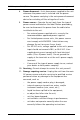
DINION capture 5000/7000 1.4 Safety | en 13 FCC & ICES compliance FCC & ICES Information (U.S.A. and Canadian Models Only) This device complies with part 15 of the FCC Rules. Operation is subject to the following conditions: – this device may not cause harmful interference, and – this device must accept any interference received, including interference that may cause undesired operation.
en | Safety – DINION capture 5000/7000 cet appareil ne peut pas provoquer d'interférence nuisible et – cet appareil doit pouvoir tolérer toutes les interférences auxquelles il est soumit, y compris les interférences qui pourraient influer sur son bon fonctionnement.
DINION capture 5000/7000 1.5 Safety | en 15 Bosch notices Video loss Video loss is inherent to digital video recording; therefore, Bosch Security Systems cannot be held liable for any damage that results from missing video information. To minimize the risk of lost digital information, Bosch Security Systems recommends multiple, redundant recording systems, and a procedure to back up all analog and digital information.
en | Description 2 DINION capture 5000/7000 Description The DINION capture is a specialty camera designed to capture consistent, high-quality images of vehicle license plates. Available in IP and analog versions, it is ideal for monitoring parking lots, public areas, and for controlling vehicle access. The DINION capture overcomes the problems encountered when using conventional surveillance cameras in vehicle identification and automatic license plate recognition applications.
DINION capture 5000/7000 3 Installing the DINION capture | en 17 Installing the DINION capture This section provides instructions for mounting and wiring the DINION capture. CAUTION! The selected mounting location should not place the camera in a situation where its environmental specifications could be exceeded. Ensure the selected location is protected from falling objects, accidental contact with moving objects, and unintentional interference from personnel. Follow all applicable building codes. 3.
en | Installing the DINION capture Model DINION capture 5000/7000 Capture Optimal Range Distance HFOV VFOV VER-x2R1-1 3.8–6.4 m 4.9 m 31.9° 24.2° VER-x2R1-2 (12.5–21.0 ft) (16.0 ft) 23.0° 17.3° VER-x2R2-1 5.5–9.1 m 7.1 m 22.3° 16.8° VER-x2R2-2 (18–30 ft) (23.1 ft) 16.0° 12.0° VER-x2R3-1 7.9–13.7 m 10.2 m 15.6° 11.8° VER-x2R3-2 (26–45 ft) (33.5 ft) 11.1° 8.3° VER-x2R4-1 11.3–19.5 m 14.8 m 10.8° 8.1° VER-x2R4-2 (37–64 ft) (48.4 ft) 7.7° 5.8° VER-x2R5-1 16.
DINION capture 5000/7000 Figure 3.1 1 2 3 4 Installing the DINION capture | en 19 Recommended Vertical and Horizontal Mounting Angle DINION capture Capture Range Vertical Mounting Angle Horizontal Mounting Angle If the maximum range is exceeded, then the letters become smaller and more difficult to read. At the maximum range and angle the width of the number plate covers approximately 12% of the width of the screen.
en | Installing the DINION capture 3.3 DINION capture 5000/7000 Mounting the DINION capture CAUTION! Installation should only be performed by a qualified service professional in accordance with the National Electrical Code or applicable local codes. For a secure mounting installation, bolts should extend through the mounting surface and be secured with nuts, washers, and lock washers on the opposite side. If studs are used, they should be anchored in concrete or welded to a steel backer plate.
DINION capture 5000/7000 4. Installing the DINION capture | en 21 Secure the mounting bracket to the mounting surface. Use four (4) corrosion-resistant, stainless steel studs or bolts, nuts, washers, and lock washers (not supplied). 5. Adjust the license plate camera angle using the range and angle recommendations in Section 3.1 Determining the Range, page 17. – Connect the imager to a local monitor to assist adjusting the license plate camera. 6.
en | Installing the DINION capture DINION capture 5000/7000 NOTICE! For purposes of evaluation and testing of the mounting bracket's integrity under static loading at CSA, the unit was mounted to a drywall surface as per the procedures below: – Locate a stud in the wall and mark the outside edges of the stud. – Using the wall mount bracket as a template, align the mounting hole with the center of the stud.
DINION capture 5000/7000 3.4 Installing the DINION capture | en 23 Preparing the Wiring CAUTION! Before proceeding, disconnect the power from the power supply cable. Ensure that the voltage of the unit matches the voltage and type of the power supply being used. The DINION capture 5000 comes pre-wired with a single twowire power input lead and a single 75 ohm coaxial video cable output lead terminated with a BNC connector.
en | Installing the DINION capture 3.5 DINION capture 5000/7000 Making the Connections WARNING! Before proceeding, disconnect the DINION capture from the power supply. Ensure that the voltage of the unit matches the voltage and type of the power supply being used. The easiest way to connect the cables is as follows: 1. Bring the building connections through the surface cable hole so that they hang clear. 2. Connect the BNC connector of the license plate camera module to the video coax cable.
DINION capture 5000/7000 Installing the DINION capture | en 25 operates as desired during darker conditions but overexposes the image during sunny conditions. IMPORTANT: Only setup Automatic Mode Switching if the target license plate is in the sun and the captured image is overexposed, never setup if the license plate is in the shade. Mode Details Mode 2 (FullSun) is two (2) gain points less than the normal mode, by default.
en | Installing the DINION capture DINION capture 5000/7000 To setup Automatic Mode Switching: 1. Ensure to setup during the brightest conditions of the day, the plate image should appear very bright before setup. 2. Remove the back panel of the housing and enable the Mode ID position as shown in Mode details and complete a power cycle of the camera. 3. Locate the potentiometer on the right as shown below. 4. View the video output on a monitor. 5.
DINION capture 5000/7000 Installing the DINION capture | en 27 To disable Automatic Mode Switching: 1. Navigate to the Install menu for the license plate camera. Refer to Section 4.1 Menus, page 28. 2. Navigate to the Alarm I/O menu. 3. Select None for the Input Action option. Refer to Section 4.6.3 Alarm I/O submenu, page 47. NOTICE! Shutter can also be changed to adjust plate brightness. Shutter is fixed at 1/5000 from the factory and should be changed only by an experienced user.
en | Configuration 4 DINION capture 5000/7000 Configuration The DINION capture normally provides an optimal picture for capturing license plates without the need for further adjustments. Advanced setup options are available for getting the best results under special circumstances. The DINION capture implements changes immediately so that before and after settings are easily compared. 4.1 4.1.1 Menus Top level menus There are two upper level menus: a Main menu and an Install menu.
DINION capture 5000/7000 Configuration | en 29 To access the keypad for the license plate camera: 1. Remove the four (4) hex socket screws from the back panel using the supplied 3 mm hex key. 2. Locate the keypad inside the imager. 1 2 3 4 5 Bosch Security Systems, Inc. Up key Right key Down key Left key Menu/Select key Installation Manual | 1.0 | 2012.
en | Configuration DINION capture 5000/7000 To access the keypad for the overview camera: 1. Remove the hex socket screw from the back panel using the supplied 3 mm hex key. 2. Locate the keypad inside the imager. 1 2 3 4 5 | 1.0 | 2012.01 Up key Right key Down key Left key Menu/Select key Installation Manual Bosch Security Systems, Inc.
DINION capture 5000/7000 4.1.3 Configuration | en 31 Menu Navigation Keys Five keys are used for navigating through menu system. – Use the up or down keys to scroll through a menu. – Use the left or right keys to move through options or to set parameters. – When in a menu, quickly double-press the menu/select key – To close all menus at once hold down the menu/select key to restore the selected item to its factory default. until the menu display disappears or continually select the Exit item.
en | Configuration 4. DINION capture 5000/7000 Mode 4 Default settings. 5. Mode 5 Default settings. 6. Mode 6 Default settings. NOTICE! In the overview camera, mode names by default are called Mode 1, Mode 2, etc. 4.3 Day/Night switching (DINION capture 7000) The overview camera is equipped with a motorized IR filter. The mechanical IR filter can be removed in low-light or IR illuminated applications by software configuration settings.
DINION capture 5000/7000 4.4 Configuration | en 33 Camera control communication (Bilinx) The DINION capture is equipped with a coaxial communications transceiver (also referred to as Bilinx). In combination with VPCFGSFT, the camera setting can be changed from any point along the coaxial cable. All menus can be accessed remotely giving full control of the camera. With this method of communication it is also possible to disable the local keys on the camera.
en | Configuration 4.5 DINION capture 5000/7000 Main menu structure Refer to Section 4.1 Menus, page 28, to access the Main menu.
DINION capture 5000/7000 4.5.1 Configuration | en 35 Mode submenu Item Selection Description Mode 1 to 6 Selects operating mode. Mode ID Alphanumeric Mode name (10 characters maximum) Copy active Available Copies current mode settings to the mode mode mode number selected. numbers Default mode Submenu Restores camera to the factory default settings. EXIT 4.5.2 Returns to main menu.
en | Configuration DINION capture 5000/7000 Item Selection ALC level -15 to +15 Description Selects the range within which the ALC will operate. A positive value is more useful for low-light conditions; a negative value is more useful for very bright conditions. Some ALC adjustment may improve scene content when Smart/BLC is enabled. Peak/average -15 to +15 Adjusts the balance between peak and average video control.
DINION capture 5000/7000 4.5.3 Configuration | en 37 Shutter/AGC submenu NOTICE! Shutter settings should be changed only by an experienced user. Changing the shutter speed effects maximum capture speed of the vehicle and ambient rejection ability. The license plate camera Shutter is fixed at 1/5000 from the factory for maximum performance. The overview camera shutter is fixed at 1/500 for maximum performance (DINION capture 7000 only).
en | Configuration Item DINION capture 5000/7000 Selection Actual shutter Description Displays the actual shutter value from the camera to help compare lighting levels and optimum shutter speed during set-up. Gain control On, Fixed On - the camera automatically sets the gain to the lowest possible value needed to maintain a good picture. Fixed - sets Fixed AGC value (best performance). Maximum AGC 0 to 30 dB Selects the maximum value the gain or can have during AGC operation.
DINION capture 5000/7000 4.5.4 Configuration | en 39 Day/Night submenu (Overview Camera - DINION capture 7000 only) Item Selection Description Day/Night Auto, Color, Auto - the camera switches the IR cut- Monochrome off filter on and off depending on the scene illumination level. Monochrome - the IR cut-off filter is removed, giving full IR sensitivity. Color - the camera always produces a color signal regardless of light levels.
en | Configuration DINION capture 5000/7000 Item Selection Description IR contrast Enhanced, Enhanced - the camera optimizes Normal contrast in applications with high IR illumination levels. Select this mode for IR (730 to 940 nm) light sources and for scenes with grass and green foliage. Normal - the camera optimizes contrast in mono applications with visible light illumination. Color burst (mono) On, Off Off - the color burst in the video signal is switched Off in monochrome mode.
DINION capture 5000/7000 4.5.5 Configuration | en 41 Enhance / Dynamic Engine submenu NOTICE! The Enhance settings are factory set to work optimally for capturing license plates, only an experienced user should change these settings. Use discretion when changing settings. Item Selection Description Dynamic Off, XF-DYN, Off - turns off all automatic scene Engine 2X-DYN*, detail and enhancements SmartBLC (recommended setting for license plate camera).
en | Configuration DINION capture 5000/7000 Item Selection Black level -50 to +50 Description Adjusts the black offset level. A low (negative) value makes the level darker. A high (positive) value makes the level lighter and may bring out more detail in the darker areas. Sharpness -15 to +15 Adjusts the sharpness of the picture. A low (negative) value decreases noise but makes the picture less sharp. Increasing sharpness brings out more detail, but increases noise.
DINION capture 5000/7000 4.5.6 Configuration | en 43 Color submenu (Overview Camera - DINION capture 7000 only) Item Selection Description White balance ATW, ATW - Auto tracking white balance AWBhold, allows the camera to constantly adjust Manual for optimal color reproduction. AWBhold - Puts the ATW on hold and saves the color settings. Manual - the Red, Green, and Blue gain can be manually set to a desired position.
en | Configuration 4.5.7 DINION capture 5000/7000 VMD submenu Item Selection Description VMD Off, Silent, Off - Video Motion Detection (VMD) is OSD off. Silent - video motion generates silent alarm. OSD - video motion generates onscreen text message alarm. VMD area Submenu Select to enter the area set-up menu to define the detection area. Motion Indicates the peak of measured motion indicator in the selected area. Press either the right, left or center navigation button to reset.
DINION capture 5000/7000 Configuration | en 45 Note: When VMD is enabled, normal light fluctuations or environmental factors can contribute to false-positive alarms. Because of this, it is recommended that you do not connect the VMD-triggered alarm output of the camera to a monitored alarm system as the false-positive alarms may be considered a nuisance. 4.6 Install menu structure Refer to Section 4.1 Menus, page 28, to access the Install menu.
en | Configuration 4.6.1 DINION capture 5000/7000 Language submenu Item Selection Description Language English Displays the menus on the OSD in the Spanish chosen language. French German Portuguese Polish Italian Dutch Russian EXIT 4.6.2 Returns to Install menu. Lens Wizard submenu NOTICE! The license plate camera lens is factory calibrated and does not require any adjustments. The overview camera lens should not require any adjustments, if applicable.
DINION capture 5000/7000 Item Configuration | en Selection 47 Description Set Backfocus Select to fully open the iris. Follow the now instructions below for setting the backfocus for your particular lens type. After focusing the object of interest remains in focus under bright and low light conditions. Set LVL Only for video-iris lenses. Adjust the level control on the lens to center the level detector indicator (see below). EXIT 4.6.3 Returns to Install menu.
en | Configuration Item Alarm output DINION capture 5000/7000 Selection Description VMD, VMD: - output relay closes on VMD External alarms. device, External device: - make the output Night mode relay available to remote active, communication devices. Filter toggle Night mode active: - output relay closes when camera is in monochrome mode. Filter toggle: - output relay closes just before the IR filter starts moving and opens when video level has stabilized (2 to 3 seconds) EXIT 4.6.
DINION capture 5000/7000 Configuration | en Item Selection Description Compensation 0,1,2 . . .+15 Sets the level of cable compensation On, Off If Off, Bilinx communications is 49 level Bilinx Comms. disabled. EXIT 4.6.5 Returns to Install menu. Test signal submenu Item Selection Description Camera ID Off, On Select On to overlay the camera ID on with Test Test pattern the video test signal. Color bars Select the desired test pattern to help 100%, installation and fault-finding.
en | Configuration 4.6.6 DINION capture 5000/7000 Camera ID submenu Item Selection Description Camera ID Enter a 17-character camera name. Use Left/Right to change position in the string; use up/down to select character. Use Select to exit. Display ID pos. Off, Top left, Select the screen position of the Top right, camera ID. Bottom left, Bottom right Display mode Off, Top left, Camera mode is displayed on the ID Top right, screen in the selected position.
DINION capture 5000/7000 4.6.7 Configuration | en 51 Privacy masking submenu Item Selection Description Pattern Black, Grey, Selects pattern for all masks. White, Noise Mask 1, 2, 3, 4 Four different areas can be masked. Active On, Off Turns each of the four masks on or off. Window Submenu Select to open a window in which to define the mask area.
en | A DINION capture 5000/7000 Dimensional Drawings DINION capture 5000 452 (17.8) 340 (13.3) 263 (10.4) mm (in.) Figure 1.1 DINION capture 5000 – Side View 307 (12.1) 139 (5.5) 154 (6.1) mm (in.) Figure 1.2 | 1.0 | 2012.01 DINION capture 5000 – Front View Installation Manual Bosch Security Systems, Inc.
DINION capture 5000/7000 | en 53 DINION capture 7000 459 (18.1) 350 (13.8) 263 (10.4) mm (in.) 322 (12.7) DINION capture 7000 – Side View 307 (12.1) 139 (5.5) 94 (3.7) 269 (10.6) 16 (0.6) Figure 1.3 mm (in.) Figure 1.4 Bosch Security Systems, Inc. DINION capture 7000 – Front View Installation Manual | 1.0 | 2012.
en | | 1.0 | 2012.01 DINION capture 5000/7000 Installation Manual Bosch Security Systems, Inc.
Bosch Security Systems, Inc. 850 Greenfield Road Lancaster, PA 17601 U.S.A. www.boschsecurity.com © Bosch Security Systems, Inc.