Bosch Security Systems, Inc. 850 Greenfield Road Lancaster, PA 17601 USA Tel: 800-326-3270 Fax: 1-717-735-6560 www.boschsecuritysystems.com Bosch Security Systems B.V. P.O. Box 80002 5600 JB Eindhoven The Netherlands Tele +31 40 27 80000 © 2003 Bosch Security Systems GmbH 3935 890 11512 03-39 | September 23, 2003 | Data subject to change without notice. Bosch Security Systems Pte Ltd.
LTC 8555 Series Instruction Manual EN Allegiant® Keyboards
LTC 8555 Series | Instruction Manual | Important Safeguards Important Safeguards 1. Read Instructions - All safety and operating instructions should be read before the unit is operated. 2. Retain Instructions - The safety and operating instructions should be retained for future reference. 3. Heed Warnings - All warnings on the unit and in the operating instructions should be adhered to. 4. Follow Instructions - All operating and use instructions should be followed. 5.
LTC 8555 Series | Instruction Manual | EN | 31 Windows® and Windows NT®, are registered trademarks of Microsoft Corporation.
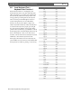
EN | 30 LTC 8555 Series | Instruction Manual | Icon Translator Chart 10 ICON TRANSLATOR CHART Ack (Applies to LTC 8555/01 and LTC 8555/03 keyboard models) The following chart is used to cross-reference the text descriptions contained in the manual with the icons found on keyboard models LTC 8555/01 and LTC 8555/03.
LTC 8555 Series | Instruction Manual | FCC & ICES Information 17. Damage Requiring Service - Unplug the unit from the outlet and refer servicing to qualified service personnel under the following conditions: a. When the power supply cord or plug is damaged. b. If liquid has been spilled or objects have fallen into the unit. c. If the unit has been exposed to water and/or inclement weather (rain, snow, etc.). d. If the unit does not operate normally by following the operating instructions.
EN | 4 LTC 8555 Series | Instruction Manual | Safety Precautions Safety Precautions CAUTION: TO REDUCE THE RISK OF ELECTRIC SHOCK, DO NOT REMOVE COVER (OR BACK). NO USER SERVICEABLE PARTS INSIDE. REFER SERVING TO QUALIFIED SERVICE PERSONNEL.
EN | 29 LTC 8555 Series | Instruction Manual | Troubleshooting 9.2 Local Keyboard Test -Keyboard User Function 1 Keyboard User Function 1 is an Allegiant system keyboard feature used to verify that all the keyboard’s LEDs and switches are in working order. This function also automatically calibrates the center position of the analog joystick. Upon starting this test, the keyboard emits a short beep and all LEDs light for about two seconds. During this time, note any LED failures.
EN | 28 LTC 8555 Series | Instruction Manual | Troubleshooting 9 TROUBLESHOOTING 9.1 General PROBLEM Possible Causes No Power Indication a) If powered from a non-modular type Allegiant, try another keyboard port on the Allegiant. The port may have failed. b) If powered from a modular type Allegiant, check the fuse on main Allegiant power supply. Try another keyboard port. c) If powered from a separate power source, check power source or main AC supply of power source.
EN | 5 LTC 8555 Series | Instruction Manual | Safety Precautions Sicherheitshinweise VORSICHT: DAS GEHÄUSE ZUR VERMEIDUNG VON ELEKTRISCHEN SCHLÄGEN NICHT ÖFFNEN. DAS GERÄT ENTHÄLT KEINE VOM BENUTZER ZU WARTENDEN TEILE. REPARATUREN NUR VON FACHPERSONAL AUSFÜHREN LASSEN. Das Blitzsymbol im gleichseitigen Dreieck soll den Benutzer auf nicht isolierte “gefährliche Spannung” im Produkt hinweisen, die ausreichend stark sein kann, um die Gefahr von elektrischen Schlägen für Menschen darzustellen.
EN | 6 LTC 8555 Series | Instruction Manual | Safety Precautions Veiligheidsmaatregelen GEVAAR: OPEN DEZE BEHUIZING NIET, TENEINDE HET RISICO VAN ELEKTRISCHE SCHOKKEN TE VOORKOMEN. BINNENIN BEVINDEN ZICH GEEN DOOR DE GEBRUIKER TE REPAREREN ONDERDELEN. RAADPLEEG VOOR REPARATIE GEKWALIFICEERD SERVICEPERSONEEL.
LTC 8555 Series | Instruction Manual | Data Interface and Cable Pinouts 8 DATA INTERFACE AND CABLE PINOUTS Keyboard 6-Pin Interface Connector Pin Connection 1 Supply voltage1 2 Gnd 3 Data -- 4 Data + 5 Gnd 6 Supply voltage1 Supplied 6-Pin Data/Power Cable (Replacement part number 303 0239 001) Side Connection Side 1 1 Supply voltage 6 2 Gnd 5 3 Data + 4 4 Data – 3 5 Gnd 2 1 6 Supply voltage 1 NOTE 1: Supply voltage varies based on Allegiant system model.
EN | 26 LTC 8555 Series | Instruction Manual | User Information No. Function Description Access Level 27. SELECT KEYBOARD LOG-IN 12 28. SELECT CONSOLE LOG-IN 12 29. RESET RS-232 PARAMETERS 12 30. SELECT CONSOLE RS-232 PARAMETERS (except LTC 8900) 12 30. SELECT CONTROLLER RS-232 (LTC 8900 ONLY) 12 SELECT PRINTER RS-232 PARAMETERS (except LTC 8900) 12 SELECT CONSOLE RS-232 (LTC 8900 ONLY) 12 32. SELECT ALARM RS-232 PARAMETERS 12 33.
EN | 7 LTC 8555 Series | Instruction Manual | Safety Precautions Medidas de Segurança CUIDADO: PARA REDUZIR O RISCO DE CHOQUE ELÉCTRICO, NÃO ABRA AS TAMPAS. O INTERIOR NÃO CONTÉM PEÇAS QUE NECESSITEM DE MANUTENÇÃO. A MANUTENÇÃO DEVE SER EFECTUADA POR PESSOAL DE ASSISTÊNCIA TÉCNICA QUALIFICADO.
LTC 8555 Series | Instruction Manual | Contents EN | 8 Table of Contents Important Safeguards . . . . . . . . . . . . . . . . . . . . . . . . . . . . . . . . . . . . . . . . . . . . . . . . . . . . . . . . . . . . . .2 FCC Information . . . . . . . . . . . . . . . . . . . . . . . . . . . . . . . . . . . . . . . . . . . . . . . . . . . . . . . . . . . . . . . . .3 1 UNPACKING . . . . . . . . . . . . . . . . . . . . . . . . . . . . . . . . . . . . . . . . . . . . . . . . . . . . . . . . . . . . . .
EN | 25 LTC 8555 Series | Instruction Manual | User Information 7.5.17 Programming a SalvoSwitching Camera Sequence A SalvoSwitching® sequence allows specification of a group of monitors that will switch together as a synchronized group. To program a salvo sequence, enter the programming mode as described above for a simple camera sequence. Since a salvo sequence involves multiple monitors switching as a group, the sequence must involve more than 1 monitor.
LTC 8555 Series | Instruction Manual | User Information Consider a sequence as being similar to a spreadsheet; a simple sequence would consist of 3 columns of information that would look as follows: CAMERA MONITOR DWELL 1 1 2 2 1 2 3 1 2 4 1 2 5 1 2 Programming of sequences can best be described by going through the above example. Initiate the programming mode by pressing PROGRAM.
EN | 9 LTC 8555 Series | Instruction Manual | Unpacking 1 UNPACKING This electronic equipment should be unpacked and handled carefully.
EN | 10 LTC 8555 Series | Instruction Manual | Installation 5 INSTALLATION ALLEGIANT 5.1 User Monitor Set Shot Prog Lock Camera Seq On Off Run 1 2 3 Next 4 5 6 Prev Alarm 7 8 9 Hold Ack 0 Clear Enter Focus Iris ALLEGIANT 1 2 3 4 5 6 7 8 9 0 4 General The maximum number of keyboards that can be connected to an Allegiant system depends on the Allegiant model.
EN | 23 LTC 8555 Series | Instruction Manual | User Information 7.5.12 Load/Clear a Sequence To load a previously programmed sequence so it can be run on your monitor, press SEQUENCE, enter the desired sequence number (1 to 60 for most Allegiant models, or 1 to 256 for the LTC 8900 system), and then press ENTER. Note that loading a sequence does not automatically initiate the sequence. Refer to the following sections for sequence control information.
EN | 22 LTC 8555 Series | Instruction Manual | User Information To turn off an auxiliary function of a remote camera device, press OFF, enter the number of the auxiliary to be deactivated, then press ENTER. With AutoDome cameras, auxiliary commands are used to activate/deactivate certain operational features and functions. Refer to the manual supplied with the AutoDome camera for complete information on supported features.
EN | 11 LTC 8555 Series | Instruction Manual | Installation The Allegiant Switcher supports several options affecting keyboard operation: • login security mode setting • enabled / disabled keyboard ports • fixed or variable speed communication protocol setting These options are selected via Allegiant CPU dipswitch settings, Allegiant Keyboard User Functions, or via options in the PC based Master Control Software package.
EN | 12 LTC 8555 Series | Instruction Manual | Installation Allegiant Keyboard Port Allegiant system main CPU bay 3 m (10 ft) data/power cable (supplied with keyboard) Figure 1: Typical Configuration using supplied data/power cable Allegiant Keyboard Port Allegiant system main CPU bay Optional LTC 8558/00 30 m (100 ft) data/power cable Figure 2: Typical Configuration using optional LTC 8558/00 cable For connections beyond 30 m (100 ft), the LTC 8557 Series Remote Hookup Kit can be used, as shown in FI
EN | 21 LTC 8555 Series | Instruction Manual | User Information 7.5 7.5.1 Keyboard Operating Instructions Camera Selection Enter a valid camera number via the numeric keypad and press ENTER. The selected camera then appears on the monitor currently controlled by the keyboard. NOTE: The keyboard's CAMERA button does not need to be used for simple camera selections.
EN | 20 LTC 8555 Series | Instruction Manual | User Information 7 7.1 General The Allegiant system is factory-supplied with various user-selectable features set to their default states (the main Allegiant system Installation Manual contains complete descriptions). Since these features are userselectable and have a significant effect on system behavior, some of the descriptions below may not apply to your system configuration. 7.2 9.
EN | 13 LTC 8555 Series | Instruction Manual | Installation The larger Allegiant models support Keyboard Expander accessory units. These accessory units are used with LTC 8557 Series Remote Hookup Kit, to provide additional keyboard connections to the system, as shown in FIGURE 5.
EN | 14 LTC 8555 Series | Instruction Manual | Installation 5.3.3 Allegiant System Command Scripts for RS-232 Model Keyboards When a keyboard is being connected to an Allegiant’s Console port, or an Allegiant Printer port configured to operate in the Console mode, the Allegiant must be preprogrammed so the port will operate in the RS-232 keyboard mode.
EN | 19 LTC 8555 Series | Instruction Manual | Keyboard Controls 6.5 5.3.6 Login Feature When Using RS-232 Model Keyboards The Allegiant’s keyboard login feature is not affected by use of RS-232 keyboards. If desired, this feature can be enabled to provide additional security to the system. Note that it is not possible to use the Allegiant’s Console port login feature. The RS-232 keyboards must have unrestricted access to the Allegiant’s RS-232 ports. 6 6.
EN | 18 LTC 8555 Series | Instruction Manual | Installation To convert an Allegiant Console port using a CPU dipswitch method, set dipswitches 3 and 4 to the ON position on CPU dipswitch S100, S1001, or S0201 (the switch number depends on the Allegiant model being used). After a system reset (power off/on, for example), the Allegiant’s Console port is forced into the Port Expander mode, and the RS-232 data rate is automatically set to 57,600 baud.
EN | 15 LTC 8555 Series | Instruction Manual | Installation If using the LTC 8059 Master Control Software, while online, select the Command Script tab and enter the script for your connection type exactly as it appears in the table below: Keyboard interface connection type Direct to Console port (except LTC 8900) Command Script Begin @boot SET-PORT-RS232 0 4 8 0 1 0 _SET_KBD_MODE 0 1 break Direct to Printer port (except LTC 8900) Begin @boot SET-PORT-RS232 4 4 8 0 1 0 _SET_KBD_MODE 4 1 break Modem conn
EN | 16 LTC 8555 Series | Instruction Manual | Installation 5.3.4 Modem Interface Information When Using RS-232 Model Keyboards RS-232 model keyboards can be connected to an Allegiant via dial-up modem link. The keyboard supports a rudimentary ability to dial a phone number of an attached modem. Further details for the dial-up feature will follow, in the operating instructions. FIGURE 7 shows a typical system configuration using a modem connection.
EN | 17 LTC 8555 Series | Instruction Manual | Installation The modem on the Allegiant side must be set to an auto answer mode, and the modem on the keyboard side must be set to an originate mode. In some cases, modem settings are configured via dipswitches found on the back of the modem. In other cases, the modem must be connected to a PC for configuration. The below settings represent the dipswitch configuration required for US Robotics Sportster modems.