DISHWASHER Installation Instructions LAVE-VAISSELLE Instructions d’installation LAVADORA DE PLATOS Instrucciones de instalación Cycle Countdown Power Scrub Plus On/Off Scrub Wash Regular Wash Delicate/ Econo Quick Wash Rinse & Hold Refill Rinse Agent On /Off Power Scrub Power Delay Start Hours Top Rack Only Rinse & Hold Cancel Drain Regular Wash Cycles SHV 6800, 4800,4300 SHI 6800,4300 SHU 9950, 9920, 9910, 8810, 8800, 6800, 5300, 4320,3300, 3131, 3030 Power High Temp Wash Regular Temp W
INTRODUCTION .................................................. .2 TOOLS AND MATERIALS NEEDED ......................... .3 MATERIALS SUPPLIED.......................................... .4 CHOOSING LOCATION ........................................ .5 PLUMBING PREPARATION .................................... .6 ELECTRICAL PREPARATION .................................. .7 PLACING THE DISHWASHER ................................ .8 DRAIN HOSE CONNECTION ................................. .9 HOT WATER CONNECTION ..
INTRODUCTION THESE INSTALLATION INSTRUCTIONS ARE INTENDED FOR USE BY QUALIFIED INSTALLERS. In addition to these instructions the dishwasher shall be installed: • • In the United States, in accordance with the National Electric Code/State and Municipal codes and/or local codes. In Canada, in accordance with the Canadian Electric Code C22.1 -latest edition/Provincial and Municipal codes and/or local codes. Please read these installation instructions completely and carefully.
TOOLS & MATERIALS NEEDED Tools Needed for Installation Hole saw or 1 hole cutter Pipe wrench, 2 reqd. Tape Measure Slotted screwdriver (#2) Adjustable wrench, (size med., 2 reqd.) Wire Cutter Phillips screwdriver (#2) Torx screwdriver, #20 Wire stripper ENGLISH Hammer Electric Drill Level Figure 1 Materials Needed 1 Electric Connection - 2 conductor, 1 ground insulated electrical supply cable (30” or sufficient length for your installation). 2 Hot Water Supply Line - Minimum 3/8” O.D.
MATERIALS SUPPLIED Accessory Parts Supplied Accessory Parts for your model dishwasher will come in one or more plastic bags. Check to make sure that the parts supplied for your model are all there. See Figure 3. If any parts are missing, stop the installation and contact your dealer immediately. DISHWASHER INSTALLATION KIT (Clear Bag) D. E. F. G.
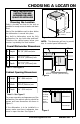
CHOOSING A LOCATION 3-1/2” (90mm) Choosing the Location Select a location as close to the sink as possible for ready access to water and drain lines. Most of the installation work is done before the dishwasher is moved into place. Any built-in dishwasher must be fully enclosed on the top, both sides and back. Therefore the cabinet space below your counter is probably the best location.
PLUMBING PREPARATION THESE INSTALLATION INSTRUCTIONS ARE INTENDED FOR USE BY QUALIFIED INSTALLERS Drain Hose The dishwasher comes with a seven (7) foot drain hose. • A 1.25” access hole must be made to allow the drain hose to be run to the drain connection location. CAUTION To protect against possible rupture of the fill valve, water lines leading to the dishwasher, as well as water lines in the dishwasher MUST be protected against freezing. If the valve or water line freezes, flooding may occur.
ELECTRICAL PREPARATION WARNING 24”-24-1/4” 23-5/8" - 24-1/8" (610-616mm) (600-613 mm) 3-1/2 (90 mm) Electrical Supply It is the customer’s responsibility to insure that the dishwasher installation is in compliance with all national and local electrical codes and ordinances. The dishwasher is designed to operate with a 120V, 60Hz, AC only electrical supply. Connect to a separate electrical circuit with a fuse or circuit breaker rated for 15 Amps.
PLACING THE DISHWASHER Placing the Dishwasher The profile strips on the sides of the dishwasher allow the dishwasher to fit into a cabinet opening with a width of 24” (610 mm) to 24-1/4” (616 mm). Before sliding the dishwasher into the cabinet opening: • • • • • Straighten the hot water supply line and the electrical cable (see Figure 11). Level & Align (initial adjustments). Guide the drain hose carefully (avoiding kinks in hose) as the dishwasher is slid into the cabinet opening.
DRAIN HOSE CONNECTION Drain Hose in Sink with Air Gap/ No Disposer Drain Hose Drain Hose in Sink with Air Gap & Disposer Openings for drain lines must be installed in the marked areas as shown in Figures 8 and 9 to avoid interference with the dishwasher frame or other components. CAUTION Trap Figure 12 min. 20” (500 mm) clearance to floor • Before beginning, turn off the water supply! • The access hole for the drain hose should be 1.25” (32 mm) diameter.
HOT WATER CONNECTION THESE INSTALLATION INSTRUCTIONS ARE INTENDED FOR USE BY QUALIFIED INSTALLERS Shut off valve (not included) Connecting the Hot Water Supply Line • If using a solder joint instead of a compression fitting, be sure to make all solder connections before connecting the water line to the dishwasher. • Make sure there are no sharp bends or kinks in the water line which might restrict water flow. • When connecting threaded pipe use pipe thread compound or Teflon tape to seal the connection.
ELECTRICAL SUPPLY CONNECTION Connecting Electrical Supply Be sure to follow all local and national electrical codes and ordinances. Wire nuts NEED to have metal inserts! DO NOT twist wires together before installing wire nuts. • Install strain relief or conduit connector into opening on J-box. • Strip the insulated wires, being extremely careful not to strip too much insulation. • Insert and securely fasten into strain relief, two-conductor supply cable with ground.
DOOR PANEL INSTALLATION Accessory Panel Installation SHU Models If you have an SHU model (other than the SHU 9910, 9920 or 9940 models) and have ordered an accessory panel kit it must be installed prior to sliding the dishwasher into place. Dimensions of panel size that may be used is shown in Figure 19.
DOOR PANEL INSTALLATION 1/4” max. (6 mm) ENGLISH SEE FOLDED PANEL INSTALLATION TEMPLATE SHEET FOR STEP BY STEP INSTRUCTIONS ON HOW TO INSTALL YOUR DISHWASHER PANEL(S). 25” (636 mm) 23-1/16” (586 mm) Figure 19 IMPORTANT Do NOT Drill Completely through your custom door panel. EXTENSION "A" MAX.-MIN. "B" "C" MAX.-MIN.
FINAL ADJUSTMENTS Door Tension Adjustment (only in SHI and SHV models) After installation of the dishwasher, open and close the door several times to make sure that it does so with ease. If the door closes too quickly or if the door falls open, the spring tension needs to be adjusted. • • To Adjust the Spring Tension Obtain Spring Tension Screws (2) out of the SHI/SHV parts bag (see Figure 3). Insert the screws in the right and left sides and adjust spring tension as shown (see Figure 22).
BASE AND TOE PANEL SHU 6800 Series Base and Toe Panel Installation Steps SHU6800 BASE PARTS Installation Parts SHU 6800 Base Part Base Part Screws SHU 6800 Toe Panel SHU Toe Panel Screws SHU 6800 Installation Kit (Refer to “Materials Supplied” section) SHU6800 Base Part Base Part Screws (1lft &1rgt) (attached) Toe Panel Junction Box Cover and Screw Remember to carefully check, the “Materials Supplied” section against the SHU6800 Installation Kit bag and contents.
TOE PANEL AND HANDLE Regular Toe Panel Installation (for models other than SHU 6800) • Obtain Toe Panel Screws from the Dishwasher Installation Kit bag (see Figure 3). • Insert screws through the Toe Panel. • With a Torx screwdriver, fasten screws Figure 27 and toe panel into dishwasher base. SHU 9910/9920/8800/8810 Handle Assembly The SHU 9900 model has a handle that needs to be assembled onto the door panel. Reference installation kit and instructions provided with the handle. Refer to Figures 29 and 30.
FINAL CHECKLIST Final Checklist ENGLISH Check Electrical Requirements. Be sure you have correct electrical supply and recommended grounding method. Turn on the hot water shut-off valve and electrical supply. Water temperature should be 140°F (60°C). Operate the dishwasher through one cycle and check for plumbing leaks. If the dishwasher does not operate properly, refer to the SELF- HELP, CUSTOMER SERVICE and WARRANTY sections in the Use and Care Manual.
56 02 04 2334 (8108)/ CS Part # 481829