
user manual


RAID Subsystem DVA-08K | Installation Manual Subsystem Maintenance | en 43
Bosch Security Systems F.01U.027.797 | V2 | 2008.08
6.2 Replacing Controller Module Components
6.2.1 Overview
The controller module should never be removed unless the following replaceable components
need to be accessed:
• Cache memory DIMM module: If a larger capacity DIMM module is required.
• Controller module itself: If the controller module in a single-controller model fails, it is
necessary to power down the subsystem and replace the controller.
If a DIMM module or RAID controller fails, contact your vendor immediately for a replacement.
To replace any of these components, the controller module must first be removed from the
subsystem.
6.2.2 Notes on Controller Module Maintenance
• The controller module contains a DIMM module. It is not recommended to re-use the
DIMM module extracted from a failed controller unless you have a similar RAID subsystem
that can be used to test the module. You can contact your vendor for sending the failed
controller in for repair.
• When replacing the controller module, it must be remembered that the controller board
is one of the most sensitive components in the subsystem. All previously stipulated safety
precautions must be strictly adhered to. Failure to adhere to these precautions can result
in permanent damage to the controller board, resulting in lengthy delays.
• Prior to replacing the controller module, it is imperative for your own safety to be sure no
power is being supplied to the system.
6.2.3 Removing the Controller Module
To remove the controller module:
1. Stop host I/Os or host applications to avoid losing data or causing data inconsistency.
2. Turn the subsystem power off: If possible power off the subsystem in the way described
in Chapter 4. If it is not possible to do this turn off both PSU modules and disconnect the
power cords.
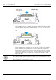
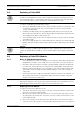
3. Disconnect all cables: There may be a number of different cables attached to the control-
ler module. These cables could include SCSI cables for host connections, an RS-232C
(audio jack) cable for serial port connection, and an Ethernet cable for network connec-
tion. Prior to removing the controller module, all these cables should be removed.
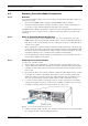
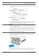
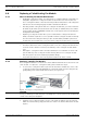
4. Loosen the retention hand screws: Hard screws are located on both sides of the RAID
controller’s faceplate. Press these screws and use a Phillips screwdriver to loosen them
so that the controller can be removed from chassis. (See Figure 6.1)
Fig. 6.1 Loosen Controller Module Retention Screws
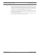
5. Pull the controller module out: Once the retention screws have been removed; gently pull
the controller module out of the subsystem chassis.