EX36‑IP No-Grip Corner Mount Camera EX36-IP en Installation Manual
EX36-IP | en 1 Important safety instructions Type numbers: NEC-360F02-11 |NEC-360F02-21 |NEC-360F04-11 NEC-360F04-21 INEI-368F04-11 |NEI-368F04-21 |NEI-368F04-11 NEI-368F04-21 INEI-369F02-11 |NEI-369F02-21 |NEI-369F04-11 NEI-369F04-21 Read, follow, and retain all of the following safety instructions. Heed all warnings on the unit and in the operating instructions. 1. Cleaning - Unpower the unit before cleaning. Follow any instructions provided with the unit.
2 en | 8. 9. 10. EX36-IP - liquid has been spilled in or on the equipment; - an object has fallen into the unit; - unit has been dropped or the unit cabinet is damaged; - unit exhibits a distinct change in performance; - unit does not operate normally when the user correctly follows the operating instructions. Safety check - Safety checks should be performed upon completion of service or repairs to the unit to ensure proper operating condition.
EX36-IP | en 3 The full version Installation Manual is available on the enclosed CD-ROM and can be viewed and printed out with Acrobat Reader, which is also on the enclosed CD-ROM. This user guide is the intellectual property of BOSCH Security Systems and is protected by copyright CAUTION! – Camera Grounding - For mounting the camera in potentially damp environments, ensure to ground the system using the ground connection of the power supply connector (see section: Connecting external power supply).
4 en | 1.1 EX36-IP Unpacking Parts list (items supplied with unit) - EX36IP Infrared Imager™ Assembly - Installation Instructions booklet - Allen Key - Software CD Items required for installation (not supplied with units) - Mounting hardware - Mounting tools - PC/Laptop with RJ45 Ethernet port - Power supply 1.2 Initial Preparations 1.) Determine the operating voltage at the installation site. The camera‘s Voltage Regulator Board accepts 12-24VAC / VDC input without change to internal connections. 2.
EX36-IP | en 5 2.) Use the supplied “security” Allen wrench to remove the six screws holding the faceplate to the housing. 3.) Remove the square foam cushion attached to the camera lens. 4.) Ensure the polycarbonate windows in the faceplate are not scratched. Housing Faceplate Tamper resistant Allen screws Tamper resistant Allen screws 2.
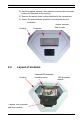
6 en | EX36-IP This view shows the interior layout of the EX36IP Camera assembly after the faceplate has been removed. 2.3 Camera: Mounting and setup: Select a suitable location that protects the camera from accidental damage, tampering and environmental conditions exceeding the specifications of the camera to be mounted. ! CAUTION! Ensure the selected location is protected from falling objects, accidental contact with moving objects and unintentional interference from personnel.
EX36-IP | en 7 Mounting holes 2.2) Camera connections and settings Remove the two screws securing the Camera / LED module assembly to the housing. Gently remove the module from the camera housing. Camera board Foam pad Analog video connection Photocell adjustment pot IR adjustment pot 2.3) LED array-power adjustments The EX36IP needs to be powered-up while making the LED power adjustments. Cover the photocell to turn the LEDs Bosch Security Systems Quick Install MAN36IPB Rev.0 | 2008.
8 en | EX36-IP Ethernet connector “ON” (850nm LEDs will have a slight red glow). Adjust the LED power if they are too bright or too dim. For IR power adjustment, rotate VR1. Clockwise is high and counterclockwise is low. 2.4) Photocell adjustment The photocell is factory set optimum level. In some conditions such as with bright foreground objects the camera may switch too early or too late. For photocell “On/Off” light-level adjustment, rotate IR Adjustment Pot.
EX36-IP | en 9 3.) Launch Configuration Manager or web-browser. 2. 4 Camera-directional adjustments Both the camera and the LED array can be adjusted for optimum picture quality. The camera lens can be tilted on its axis via two adjustment screws on the mounting bracket. It can also be moved closer or farther away from the viewing window. Connect the Ethernet and power wires. Mount the Camera/LED Array Assembly into the housing. Check the picture for quality and directional alignment.
10 en | i Note: Use Infra-Red Pass filter to cover the lens during focusing to EX36-IP simulate low light conditions on scene for correct 24-hour focusing. For camera with manual iris lens, the camera should be focused with 2.) Attach the faceplate to the camera housing. Insert and tighten the the lens iris fully opened to simulate the worst possible depth of field. 6 bolts. Using a Infra-Red Pass filter will ensure the iris is fully open for 3.) Power-up the camera and check its operation.
Americas Bosch Security Systems, Inc. 850 Greenfield Road Lancaster, Pennsylvania 17601 USA Telephone +1 888-289-0096 Fax +1 585-223-9180 Email: security.sales@us.bosch.com www.boschsecurity.us Europe, Middle East, Africa: Bosch Security Systems B.V. P.O. Box 80002 5600 JB Eindhoven, The Netherlands Phone: + 31 40 2577 284 Fax: +31 40 2577 330 emea.securitysystems@bosch.com www.boschsecurity.