Fire Alarm Control Panels FPD-7024 en Installation and Operation Manual
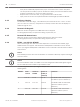
Fire Alarm Control Panels Table of Contents | en 3 Table of contents 1 Notices 6 1.1 FCC Compliance Notice 6 1.2 FCC Phone Connection to Users 6 1.3 Industry Canada Notice 7 1.4 Trademarks 7 2 Overview 8 2.1 System overview 8 2.2 Components 9 2.2.1 On-board conventional points 9 2.2.2 Off-board addressable points (with D7039 Multiplex Expansion Module) 9 2.2.3 Enclosure Housing 10 2.2.4 Remote LCD Keypads 10 2.2.5 Remote LED Annunciators 10 2.2.
en | Table of Contents Fire Alarm Control Panels 6.2 Basic System Use 38 6.2.1 Function keys 38 6.2.2 Selecting menu items 38 6.2.3 After a Main Menu item is selected 38 6.2.4 Returning to an earlier screen 38 6.2.5 Entering data 38 6.2.6 Drill 38 6.2.7 Disable 38 6.2.8 History 39 6.2.9 Remote Programming 40 6.3 Keypads 40 6.3.1 Built-in keypad 40 6.3.2 FMR-7033 keypad 42 6.4 Testing 43 6.4.1 Walk test 43 6.4.2 Communicator test 43 6.4.
Fire Alarm Control Panels Table of Contents | en 5 8.4.2 Point function 70 8.4.3 Point copy 72 8.5 PROG OUTPUTS 73 8.5.1 Programming NACs 73 8.5.2 Programming relays 76 8.6 PROG ACCOUNTS 77 8.6.1 Phone Numbers/IP Addresses 78 8.6.2 Phone Control 82 8.6.3 Report Steering 83 8.6.4 Ring Count 84 8.6.5 Communication Tries 85 8.6.6 Machine Bypass 85 8.6.7 ALT. COMM 85 8.7 PROG FORMATS 85 8.7.1 4/2 Zone Report 86 8.7.2 4/2 Report Codes 87 8.7.
1 1.1 en | Notices Fire Alarm Control Panels Notices FCC Compliance Notice This equipment was tested and found to comply with the limits for a Class A digital device, pursuant to Part 15 of the FCC Rules. These limits are designed to provide reasonable protection against harmful interference in a residential installation.
Fire Alarm Control Panels 1.3 Notices | en 7 Industry Canada Notice The Industry Canada label identifies certified equipment. This certification means that the equipment meets certain telecommunications network protective, operational, and safety requirements. Industry Canada does not guarantee the equipment will operate to the user’s satisfaction. Before installing this equipment, users should ensure that it is permissible to be connected to the facilities of the local telecommunications company.
2 2.1 en | Overview Fire Alarm Control Panels Overview System overview The FPD‑7024 Fire Alarm Control Panel is a fully integrated hard-wire fire alarm system. It can support four input points (expandable to 255 using D7039 Multiplex Expansion Module and the FPC‑7034 Four-Point Expander) and 16 individual users (expandable to 100 with the D7039). The control panel has a built-in LCD keypad.
Fire Alarm Control Panels Overview | en 4 Zone input terminal strip 10 NAC terminal strip 5 Option bus terminal strip 11 Auxiliary power terminal strip 9 6 FPC-7034 point expander connector pins 2.2 Components 2.2.1 On-board conventional points All on-board points and points implemented with the FPC-7034 work with two- or four-wire detectors. The system has an optional alarm verification feature.
en | Overview Fire Alarm Control Panels – Each point is individually supervised for proper connection to the common bus (when over ten points are troubled, up to ten troubles are shown per bus and the balance of the troubles is indicated by a common bus failure message). 2.2.3 – Response time can be set to fast, or programmed from 1 to 89 seconds. – Input points on the SLCs are implemented with a D7042 Eight Input Remote Module. Enclosure Housing The standard enclosure is 18 ga.
Overview | en Fire Alarm Control Panels D7030X zones shown on shown on covered D7030X D7032 (if 11 comments attached) 4 49 to 64 49 to 56 57 to 64 Combination with fourth lowest option bus address (such as Address 4) 5 1 to 16 1 to 8 9 to 16 Fifth combination repeats first combination 6 17 to 32 17 to 24 25 to 32 Sixth combination repeats second combination 7 33 to 48 33 to 40 41 to 48 Seventh combination repeats third combination 8 49 to 64 49 to 56 57 to 64 Eighth combin
en | Overview Fire Alarm Control Panels Communicator 2.2.7 The communicator can report to two phone numbers or IP addresses with full single, double, and back-up reporting. Communicates in SIA, Modem IIIa2, Contact ID, BFSK, and 3/1 and 4/2 Tone burst formats (available communication formats depend on phone or IP connection). i Notice! The communicator must be enabled and configured to operate. The communicator and phone line monitors are disabled in the default factory configuration.
Fire Alarm Control Panels Overview | en 13 Figure 2.2: Supplemental Reporting 1 Jumper from R1 to R2 3 House phone 2 Jumper from T1 to T2 4 TELCO line Users 2.2.8 The system allows up to 16 individual users, or up to 100 users when the D7039 is installed. A personal identification number (PIN, the four-digit code entered at the keypads) and an authority level to determine which functions can be performed can be assigned to each user. For PINs, see Personal identification numbers (PINs), 47. 2.2.
en | Overview Fire Alarm Control Panels Device Quantity Standby existing/device FMR‑7036 Total Alarm existing/ Total alarm standby device 80 mA 100 mA 27 mA 132 mA 35 mA 175 mA 35 mA 175 mA 1 mA 90 mA 80 mA 100 mA 150 mA 150 mA 18 mA 18 mA 0.50 mA 0.56 mA 0.50 mA 0.56 mA 0.55 mA 0.55 mA 0.55 mA 0.55 mA 0.55 mA 0.55 mA 0.55 mA 0.
Fire Alarm Control Panels Overview | en Device Quantity Standby existing/device D7053 MUX I/ O Total Alarm existing/ Total alarm standby device 0.70 mA 0.70 mA Grand Total Grand Total Standby Existing Alarm Existing 15 Module Fire Smoke Detectors Bells, Horns, and so on Other Sensors Other 1 The 24 VDC existing requirements for the D7030X, FMR-7033 and D7035 are shown at 75% of the 12 VDC level shown on the specification sheets for these models.
en | Overview 2.2.11 Fire Alarm Control Panels Required batteries for existing load Use the following procedure to determine the battery requirements for your system: – Estimate the size of the battery required to support the standby load using the following table: Standby load battery Capacityr required Capacity required for Capacity required for size chart for 24 hours 48 hours 60 hours 100 to 200 mA 5.8 11.5 14.4 201 to 300 mA 8.6 17.3 21.6 301 to 400 mA 11.5 23.0 28.
Fire Alarm Control Panels – Overview | en 17 Select the next larger standard battery for the system. If the results show a requirement for a battery over 40 Ah, reduce the existing load or add an external regulated fire protective signaling power supply. 2.2.12 Compatible devices Device Function D7030 Eight Point LED Identifies the location of a fire alarm for up to eight zones Annunciator allowed per system.
en | Overview Fire Alarm Control Panels Device Function D7039 Multiplex Expansion Provides either 2 two-wire (Class B, Style 4) multiplex Module buses or 1 four-wire (Class A, Style 6) multiplex bus. In Class A mode, up to 120 addressable points can be added. In Class B Mode, up to 247 addressable points can be added. The D7039 connects directly to the control panel. One is allowed per system. D7042/B Eight‑Input Remote Provides eight Class B, Style 4 input points.
Fire Alarm Control Panels Overview | en 19 Table 2.8: Compatible devices Install D7042 modules only at addresses: 9 17 25 33 41 49 57 65 73 81 89 97 105 113 121 129 137 145 153 161 169 177 185 193 201 209 217 225 233 241 Do not install D7052 and D7053 modules at these addresses: 16 24 32 40 48 56 64 72 80 88 96 104 112 120 128 136 144 152 160 168 176 184 192 200 208 216 224 232 240 248 255 Table 2.
en | Fire Safety 3 Fire Alarm Control Panels Fire Safety Danger! No fire detection device or system is 100% foolproof. This fire alarm system can provide early warning of a developing fire. Such a system, however, does not ensure protection against property damage or loss of life resulting from a fire. Any fire alarm system can fail to warn for any number of reasons (such as smoke not reaching a detector that is behind a closed door).
Fire Alarm Control Panels Fire Safety | en 21 Figure 3.1: Smoke detector locations in residential settings 3.2 1 Bedroom 5 Basement 2 Hall 6 Recreation room 3 Living room 7 Kitchen 4 Dining room * Smoke detector Having and practicing an escape plan A fire warning can be wasted unless the personnel planned in advance for a rapid and safe exit from the building. Draw a floor plan of the entire building showing two exits from each sleeping area and two from the building.
en | Installation Fire Alarm Control Panels 4 Installation 4.1 Installation guide for UL Listed systems 4.1.1 FPD‑7024 UL Listings The FPD‑7024 is UL Listed for the following: – Commercial Fire Alarm (UL Standard UL864) – Type Service: Auxiliary, Local, Central Station, and Remote Station – Type Initiating: Automatic, Manual, Sprinkler Supervisory, and Waterflow Install the control panel according to NFPA 72 for Commercial Fire installations. 4.1.
Installation | en Fire Alarm Control Panels 23 Timer Programming – Program Auto Silence Time for not less than five minutes, or to “0” to disable auto-silence operation. Point Programming – For fire points: open = trouble, latching. Alarm Output Programming – Program notification appliance circuits to activate from the appropriate input points. Communications Programming – If used for Central Station Service, select a communication format compatible with the central station.
en | Installation Fire Alarm Control Panels Figure 4.1: Wiring the D132B smoke power reversing module 1 Power limited and supervised 7 12/24 VDC 2 Optional alarm latch 8 24 V reversing detectors 3 Loop 9 2.
Fire Alarm Control Panels Installation | en 25 Figure 4.2: Wiring the D185 1 D185 module 5 Fire control panel 2 To monitoring station bk black 3 D275 bu blue 4 2.2 kΩ EOL ye yellow The module can signal alarm, trouble, and supervisory conditions. The Wiring the D185 figure, 24 shows the module being used to signal alarm and trouble conditions only. With a third relay (available from the eight-relay expansion module) and an additional leased line, supervisory conditions can also be signaled.
en | Installation Fire Alarm Control Panels 5. Install and tighten the remaining two screws in the bottom mounting holes. 6. Knock out the desired wire entrances on the enclosure. For mounting hole locations, see the following figure: Figure 4.3: Enclosure iInstallation 1 Control panel location 5 Transformer 2 Mounting holes 6 Stud 3 Retainer holes for standoffs 7 Ground wire 4 Retainer holes for support posts i 4.
Fire Alarm Control Panels Installation | en 27 Warning! ! Before the circuit board is installed, connect the supplied ground wires between the door and the enclosure and from the transformer to the enclosure using the supplied nuts. Both grounds connect to the stud in the enclosure to the left of the circuit board. For installation illustrations, see the figures for Enclosue installation, 26 and for Standoff and support post installation, 27. 1.
en | Installation Fire Alarm Control Panels If the [*/BACK] key is not pressed during the power-up time-out period, the control panel resumes operation using the last confirmed status of the affected expander and displays an installation error condition. Warning! ! Expansion devices such as point expanders and multiplex expanders are disabled if they are removed from the control panel configuration after installation. You cannot disable supervision of these devices when they are installed.
Fire Alarm Control Panels Connection | en 5 Connection 5.1 FACP terminal connection 29 Danger! Incorrect connections may result in damage to the unit and personal injury. Warning! ! Before servicing this equipment, remove all power including the transformer, battery and i Notice! phone lines. Shared cable is not recommended for option bus, telephone or NAC wiring. Figure 5.1: Typical 2-wire smoke detector wirin (supervised)g 1 Class A, Style D 3 EOL resistor 2 Class B, Style B Figure 5.
en | Connection Fire Alarm Control Panels Notice! i All wiring except battery terminal and primary AC power is power-limited. Primary AC and battery wires must be separated from other wires by at least ¼ in. (64 mm) and tied to prevent movement. Figure 5.3: Transformer RD red BN brown supervised: YE yellow WH white BK black Figure 5.4: Input Points 2012.08 | 04 | F01U008458 Installation and Operation Manual Bosch Security System, Inc.
Fire Alarm Control Panels Connection | en Unsupervised: 31 Switched unsupervised: 1 Relay 1 4 Earth ground 2 Relay 2 5 Smoke detector 3 Relay 3 Input Points 1-4: (supervised) Points are intended for connection of normally-open/normally-closed alarm contacts. They may also be used for compatible two-wire smoke detectors. All EOL resistors are 2.21 kΩ, P/N: 25899 Bosch, UL listed. Initiating devices are Class B, Style B or Class A, Style D. Two‑wire Compatibility Identifier "A".
en | Connection Fire Alarm Control Panels DX4020, B420 models, ITS-DX4020-G Figure 5.6: Keypad Connection (supervised, Class B, Style 4, 500 mA maximum) Figure 5.7: Backup Batteries 1 Class B, Style Y supervised: 2 Class A, Style Z BAT Battery 3 Backup batteries EOL End of line i BK black RD red Notice! Unswitched unsupervised Auxiliary Power: 24 V, 1.0 A maximum (unfiltered). 2012.08 | 04 | F01U008458 Installation and Operation Manual Bosch Security System, Inc.
Fire Alarm Control Panels Connection | en 33 Danger! Explosion and burn hazard! Do not short terminals! Notification appliance circuit: NAC 1+ +24 V while in alarm; ground while in standby. NAC 1- Ground while in alarm; supervisory voltage while in standby. Notification appliance circuit: NAC 2+ +24 V while in alarm; ground while in standby. NAC 2- Ground while in alarm; supervisory voltage while in standby. Batteries: BAT - Requires two 12 V batteries in series, for a combined voltage of 24 V.
en | Connection Fire Alarm Control Panels Figure 5.8: Transformer Connections Primary: YE yellow WH white BK black 5.3 Option bus wiring requirements Use 18 AWG (1.2 mm) or larger wire to connect option bus devices to the FACP. The total length of wire connected to the option bus terminals must not exceed 4 000 ft (1 219 m), regardless of the wire gauge wire used. i i Notice! Shared cable is not recommended for option bus, addressable points bus, telephone, or NAC wiring.
Fire Alarm Control Panels Connection | en 35 Add together the alarm existing current draw by all the devices on the wiring run to determine the maximum allowed distance between the option bus terminals on the control panel and the last device on the wire run (the device farthest from the control panel). To determine the maximum allowed length for the run, add up the total alarm load for option bus devices on the wire run.
en | System Operation 6 6.1 Fire Alarm Control Panels System Operation Modes of Operation There are four modes of system operation for the FPD‑7024: normal, alarm, supervisory, and trouble. 6.1.1 Normal When the system operates normally, it shows SYSTEM NORMAL on the top line of the display, the Power LED lights steadily, and no other LEDs are lit. The bottom line indicates the existing date MM/DD/YY and time HH:MM.
Fire Alarm Control Panels 6.1.6 System Operation | en 37 Trouble When a trouble condition occurs (such as cut wiring for a point or AC power fails), the sounder beeps every 10 seconds. The Trouble LED lights and the LCD shows the trouble condition. When you back out of the detailed screen when the [4/<] key is pressed the group is entered and shows TROUBLE (XXX).
en | System Operation 6.2 6.2.1 Fire Alarm Control Panels Basic System Use Function keys A keypad that does not require a PIN number shows (under normal conditions) SYSTEM NORMAL on the top line, and existing date and time on the bottom line. On a keypad that does require a PIN number, enter the PIN number first. This enables the function keys. 6.2.2 Selecting menu items Depending on which level in the system, (menu, sub-menu, sub-sub-menu), you can select an item three different ways: 1.
Fire Alarm Control Panels 6.2.8 System Operation | en 39 History i Notice! If a system without a D7039 Multiplex Expansion Module loses all power (AC and standby battery), all history events are cleared. The HISTORY option is a chronological list of system events that occurred. Press the [History] key to HISTORY select from the Main Menu (SYSTEM NORMAL display). On an FPD-7024 FACP with a D7039 Multiplex Expansion Module, up to 499 History events are supported.
en | System Operation Fire Alarm Control Panels For additional history log ID information, see the Modem IIIa2 reporting table, 105. 6.2.9 Remote Programming Call for remote programming Phone Numbers 1 and 3 must be programmed, along with Account Code 1. The control panel calls Phone Number 3 and attempts to connect for downloading. If the control panel is already using the phone line, it sounds the three-beep error tone. This function requires an access code with programming authority (Level 1).
Fire Alarm Control Panels System Operation | en 41 Figure 6.1: Built-in Keypad 1 Green Power LED - is on when the AC power is present, and flashes when 9 [#/Enter] key - to accept data when in the programming mode. the unit is operating from battery power. 2 Yellow Trouble LED - lights when the 10 [History] key - to view system events. system detects a problem with wiring or internal circuitry.
en | System Operation Fire Alarm Control Panels 4 Yellow Silenced LED - lights when the 12 [Silence] key - mutes the bell or sirens user manually silences an alarm for an alarm condition, if the system is condition (fire or water flow), turns off so configured. when the condition that was silenced is corrected. 5 [Disable] key - used to disable or 13 [Drill] key – used to activate the NACs re‑enable inputs, NACs or relays manually. It creates a history log entry (outputs), and the dialer.
Fire Alarm Control Panels System Operation | en 43 Figure 6.2: FMR-7033 Keypad 1 LEDs 3 Keys 2 Keypad Display 6.4 Testing Select any of seven special test modes using the [Test] key on the built‑in and FMR‑7033 keypads. 6.4.1 Walk test The Walk Test allows a technician to alarm each point manually to ensure that detectors connected to a point send an Alarm report to the control panel. While in this mode, the LCD shows the system test status and the trouble sounder sounds every 10 sec.
en | System Operation Fire Alarm Control Panels Notice! i This test is available only if your system sends alarms and system information to a monitoring service, and was programmed by the security installing company to permit communicator tests. NOTICE! Warning! Reset upon termination of test ! Terminating the communicator test function (with the [*/Back] key) resets the communicator and discards all unsent reports.
Fire Alarm Control Panels 5. System Operation | en 45 Show Status: After you select a device and press [#/Enter], this test shows detailed status information for the selected device. Eight conditions (not all status conditions apply to or are supported by all devices) are shown. See the display shown below (which updates automatically every five seconds). For this option, you can view the status of any MUX device regardless of which bus you selected to test when test mode was entered.
en | System Operation Fire Alarm Control Panels Figure 6.3: Mapping inputs, zones, and outputs 1 Input Point 1 is assigned to Zone 1, mapped to NAC Point 1. 2 Input Point 2 is assigned to Zone 2, mapped to NACs 1 and 2. 3 Input Point 3 is assigned to Zone 2, 4 Input Point 4 is assigned to Zone 2, mapped to NACs 1 and 2. 5 Input Point 5 is assigned to Zone 3, mapped to NAC 2, LR 1 and RR1. 6 General Alarm Zone 63 drives LR 2. mapped to NACs 1 and 2.
Fire Alarm Control Panels System Operation | en 47 Zone Condition 61 General Waterflow (Non-silenceable). Active when any waterflow alarm is present. 62 General Trouble. Active while any system trouble is present, not active in test and programming modes. 63 General Alarm, Waterflow (non-silenceable). Active while any alarm, including supervisory, is present. Remains active even while system is silenced. Table 6.3: Pre-assigned zones 6.
en | System Operation Fire Alarm Control Panels Notice! i i To disable a phone number, set the FORMAT to 0=disable. To completely disable the communicator, set FORMAT to 0=disable for both phone numbers, and set MONITOR to 0=NO for both phone lines. Notice! Do not install this control panel on a phone line that might be required for other emergency use. When events occur, the communicator sends them to the monitoring station in priority order according to NFPA requirements.
Fire Alarm Control Panels Programming | en 49 Programming 7 Danger! Untested systems! After any programming change, and especially after remote programming changes, completely check the operation of the control panel. Hazards to life and property can result if the system is not tested to detect possible improper programming. DANGER! Warning! Improper system operation! When programming the system, enter only valid types of information within the ranges speci- ! fied in the programming table.
en | Programming Fire Alarm Control Panels Program feature or Permitted in UL864 option (Yes/No) NAC Config Yes Possible settings Settings permitted in UL864 Steady Steady Pulsing Pulsing California March California March Temporal Temporal Wheelock Wheelock Gentex System Sensor System Sensor Alarm/Trouble Open Yes Status Latching 1) Alarm 2) Trouble 2) Trouble Yes 1) Yes 1) Yes for Alarms 2) No Heartbeat Interval Yes 001 - 255 001 - 090 Ring Count Yes 00 - 15 00 PIN
Fire Alarm Control Panels Programming | en 51 Function Configuration Local only? Silenceable? Loop response 1. Pull Station Fire No No Fast 2. Smoke Fire No No Fast Reset Yes No Fast Silence Yes No Fast Supervisory No Yes Fast 6. Local Test Fire Yes Yes Fast 7. Waterflow Waterflow No No Programmed Detector 3. Reset Keyswitch 4. Silence Keyswitch 5. Supervisory Input Sensor Table 7.2: Point function characteristics Alpha programming 7.
en | Programming Fire Alarm Control Panels Key Values 7 P R S 72 8 T U V 82 9 W X Y 92 Q Z 0 0 Prog # Enters the description and returns to the programming menu. Enter * Returns to the programming menu without entering changes. Back Moves the cursor one space to the right. Silence Moves the cursor one space to the left. Disable 1 Press [1] nine times to reach this value. 2 Press the listed key four times to reach this value. Table 7.
Fire Alarm Control Panels Programming | en 53 Figure 7.1: Essential keys for alpha programming 1 Number keys (including 0) - used to enter alphanumeric values. 2 [*/Back] key - used to exit alpha programming, or exit the programming 4 [Disable] key - moves the cursor one space to the left. 5 [Silence] key – moves the cursor one space to the right. mode entirely. 3 [#/Enter] key - used to accept data when in programming mode. 7.
en | Programming Fire Alarm Control Panels BFSK Similar to the programming of system events for 4/2 formats, five system events can be programmed for two unique digits each when the BFSK format is used. This programming is done under 7- PROG FORMATS, 3- BFSK RPT CODS. The BFSK format supports only a three-digit account number. The control panel sends the first three digits that are programmed.
Fire Alarm Control Panels 7.
en | Programming Fire Alarm Control Panels Figure 7.3: Program Menu - continued For factory defaults, see Appendix D. 7.6 Shortcuts You can use shortcuts to reduce repetition and provide speedy instructions for programming the control panel. The first level in the system is the Main Menu. For all system programming, is your Main Menu choice. Therefore, the first number in the shortcut is “0”. 2012.08 | 04 | F01U008458 Installation and Operation Manual Bosch Security System, Inc.
Fire Alarm Control Panels Programming | en 57 The second level in your system provides eight options: PROG TIME, SECURITY, PROG SYSTEM, PROG INPUTS, PROG OUTPUTS, PROG ACCOUNTS, PROG FORMATS, and HISTORY DEFAULTS. When the D7039 MUX Expander is installed, a ninth option appears: PROGRAM MUX. The second number in the shortcut enters the Level 2 option and allows access to Level 3. Level 3 provides the third set of options that branch from Level 2.
en | Programming Fire Alarm Control Panels inhibited (but alarm monitoring continuing), the system indicates SYSTEM TROUBLE, RMT PRG ACTIVE during remote programming. Sounders do not activate during this mode, but other outputs programmed for Zone 62, general system trouble, do activate. Trouble conditions that occur during a remote programming session are not annunciated at the control panel until the remote programming session ends.
Fire Alarm Control Panels 8 Control Panel Programming | en 59 Control Panel Programming Main Menu: SYSTEM NORMAL SELECT: PROG/0 SELECT: ENTER/# SELECT: TEST SELECT: HISTORY SELECT: DISABLE SELECT: DRILL Programming Menu: PROG/0 1-PROG TIME 2-SECURITY 3-PROG SYSTEM 4-PROG INPUTS 5-PROG OUTPUTS 6-PROG ACC’NTS 7-PROG FORMATS 8-HISTORY DEFLTS 9-PROGRAM MUX 8.1 PROG TIME PROG TIME 1-SYSTEM 2-AUTO TEST 3-DAYLIGHT SAV 8.1.
en | Control Panel Programming Fire Alarm Control Panels AUTOMATIC TEST 1-TEST TIME 2-TEST FREQNCY Press [1] to select Test Time. The following window appears: AUTO TEST TIMEHHMM: _______ Enter the time followed by the [#/Enter] key. Test Frequency Shortcut: 0-PROG, 1-PROG TIME, 2-AUTO TEST This feature allows you to program how often the automatic test reports are sent. The first test is sent when the programmed test time matches the system time.
Fire Alarm Control Panels Control Panel Programming | en 61 2-AUTHORITY 8.2.1 Personal Identification Numbers (PINs) Programmer PIN Shortcut: 0-PROG, 2-SECURITY, 1-PINS The Programmer PIN is the code used by the installer to configure and operate the panel. Factory default code is 9876 and may be changed at any time. The following window appears: PROGRAM PINS 1-PROGRAMR PIN 2-USER PINS Press [1] for Programmer PIN.
en | Control Panel Programming Fire Alarm Control Panels PIN Authority Level Allowed Operations Maximum (1) All control panel operations, including programming and disable. Medium (2) System test modes, fire drill, reset, silence, view history. Minimum (3) Silence, view history. None (0) None. Table 8.1: PIN authority levels The following window appears: AUTHORITY USER (01 - 15) Enter the user for whom you want to program the authority level and press [#/Enter].
Fire Alarm Control Panels Control Panel Programming | en 63 This feature determines how long the smoke detector power is off after reset. No alarms are registered by the system for 5 sec after power is returned. The display scrolls through the TIMERS options. Press [1] for Smoke Reset. The following window appears: SMOKE RESET (__ ) (1-16 SECS):_______ Enter the time and press [#/Enter]. The existing setting is shown in parentheses on the first line.
en | Control Panel Programming Fire Alarm Control Panels Notice! i If the condition that caused and alarm is not corrected after an alarm is silenced (automatically or manually), the alarm sounds again after 24 hours. The system must eventually be reset after silencing to allow the alarmed zones to restore and detect new alarms. The display scrolls through the TIMERS options. Press [3] for AUTO SILENCE.
Fire Alarm Control Panels Control Panel Programming | en 65 Warning! Inoperable, unsupervised devices! ! Be sure the count of devices displayed when this operation completes matches the number of devices installed on both buses. Devices not detected during the update bus operation will not operate and will not be supervised. i Notice! These menu items are allowed only at the local keypad.
en | Control Panel Programming Fire Alarm Control Panels PIN REQUIRED? 1- LOCAL 2- REMOTE Press [1] to require a PIN at the local keypad. The following window appears: LOCAL KEYPD PIN? _______: YES(1) NO(0) Press the number key that corresponds to your selection. The existing setting is shown in front of the colon on the second line. After making your selection, the previous window appears.
Fire Alarm Control Panels Control Panel Programming | en 67 Remote programming 8.3.6 Shortcut: 0-PROG, 3-PROG SYSTEM, 7-REMOTE PGM Remote programming allows the panel to be called from a remote site by phone to reconfigure any of the programmable options. When remote programming is disabled, you can still connect to the control panel for diagnostics and to view the existing program. PIN numbers are suppressed while remote programming is disabled.
en | Control Panel Programming Fire Alarm Control Panels Pressing [Drill] retrieves the next point. For instance, if you are programming Point 2 and you press [Drill], you retrieve the setting for Point 3. Pressing [History] retrieves the previous point. For instance, if you are programming Point 2 and you press [History], you return to the setting for Point 1. Assigning point functions Shortcut: 0-PROG, 4-PROG INPUTS, 1-POINT NUMBER This feature assigns each point to one point function.
Fire Alarm Control Panels Control Panel Programming | en 69 OUTPUT ZONE ZZZ (01 - 50):_______ Press the number key that corresponds to your selection. ZZZ indicates the point being programmed. The existing setting is shown on the second line. After you set up the output zone, the previous window appears. Verification Shortcut: 0-PROG, 4-PROG INPUTS, 1-POINT NUMBER This feature resets the detector once to determine if the alarm recurs before annunciating or sending a signal.
en | Control Panel Programming Fire Alarm Control Panels Enter the description using the numeric, [Silence] and [History] keys, then press [#/Enter] to save the description. Point function 8.4.2 Shortcut: 0-PROG, 4-PROG INPUTS, 2-POINT FUNCTION There are 16 point functions, each of which has programmable features for: configuration (fire, waterflow, and so on), local only operation, silencing, and loop response.
Fire Alarm Control Panels – Control Panel Programming | en 71 AC Fault: When activating, the control panel waits for the AC Delay Timer to expire before indicating or sending a trouble condition. When the timer expires, it shows an AC Fault on the control panel and the trouble LED turns on. Enter the point number you wish to program and press [#/Enter]. The display scrolls through the PROG FUNCTION options. Press [0/Prog] to select CONFIGURE.
en | Control Panel Programming Fire Alarm Control Panels Loop response Shortcut: 0-PROG, 4-PROG INPUTS, 2-POINT FUNCTION This feature allows you to configure points to activate with standard response time (setting 1) or one system-wide programmed response time (setting 2). Enter the point number you wish to program and press [#/Enter]. The display scrolls through the PROG FUNCTION options. Press [4/<] to select LOOP RESPONSE. The following window appears: RESPNS TIME (___) 1- FAST (.
Fire Alarm Control Panels Control Panel Programming | en 73 COPY FROM POINT:_______ Enter the point you wish to copy from and press [#/Enter]. COPY TO FIRST POINT:_______ Enter the first point you wish to copy to and press [#/Enter]. COPY TO LAST POINT:_______ Enter the last point you wish to copy to and press [#/Enter]. The PROG INPUTS menu appears. This feature does not copy the description. Point copy is intended for use only on input points.
en | Control Panel Programming Fire Alarm Control Panels NAC CONFIG ( ) 1- STEADY 2- PULSING 3- CALIFORNIA MARCH 4- TEMPORAL 5- WHEELOCK 6- GENTEX 7- SYSTEM SENSOR For acceptable programming selections for UL864 9th edition Listed applications, see Programming features for UL864, 49. These selections control the pattern (code) for the selected NAC. Press the number key that corresponds with the desired pattern: – Steady: Output turns on and stays on while the NAC is active.
Control Panel Programming | en Fire Alarm Control Panels Zone Pre-Assigned Condition 52 General Fire Alarm (non-silencing) 53 General Fire Alarm, (silencing) 54 Ground Start 55 General Supervisory, (silencing) 56 General Waterflow, (silencing) 57 Communication Trouble 58 General Supervisory Alarm (non-silencing) 59 Alarm Verification 60 AC Failed 61 General Waterflow Alarm (non-silencing) 62 General Trouble 63 General Alarm, Waterflow Supervisory (non-silencing) 75 Table 8.
en | Control Panel Programming Fire Alarm Control Panels Programming relays 8.5.2 Shortcut: 0-PROG, 5-PROG OUTPUTS, 2-RELAYS The main control panel includes three on-board relays (Relay 1, Relay 2, and Relay 3). The FPD‑7024 can also support up to two D7035 Octal Relay Modules (Remote Relay 1 and Remote Relay 2), that offer a total of 16 remote relays (eight relays per module).
Fire Alarm Control Panels Control Panel Programming | en 77 Notice! i The @ x shows the address of the relay module in the system. The lower number address is Relay 1; the higher one is Relay 2.When you address a MUX Module, you assign an address. If you have a dual point, it would have two consecutive addresses. Enter the relay you wish to assign and press [#/Enter].
en | Control Panel Programming Fire Alarm Control Panels 7- ALT.COMM 8.6.1 Phone Numbers/IP Addresses Shortcut: 0-PROG, 6-PROG ACC’NTS, 1-PHONE/IP NUMS The system can be programmed with two reporting phone numbers or IP addresses. Phone/ IP #1 is used with Account Number 1; Phone/IP #2 is used with Account Number 2. Remote programming occurs on Line 1 using Phone/IP #3.
Fire Alarm Control Panels Control Panel Programming | en 79 Several keys assist when you enter phone or IP numbers. For these keys, see the following table: Press Action [SILENCE] Advance to next position [DISABLE] Go back one position [RESET] Clear position Table 8.4: Phone number assistance keys Notice! For a phone number, you must enter 1 as a prefix before the special character >.
en | Control Panel Programming Fire Alarm Control Panels For example, if the necessary wait time is 30 sec, digits 14 through 16 should be 0, 3, 0 respectively. In larger installation sites using alternate communications as a destination, set the wait time to a higher value to compensate for network congestion delays. This wait time is also used for the heartbeat acknowledge wait time.
Fire Alarm Control Panels Control Panel Programming | en 81 Anti-Replay – Digit 20, Default: 1 Digit 20 of the phone number enables the Anti-Replay Feature for central station communications. A zero in this location disables this feature. This digit is always zero in the remote programmer phone number. The purpose of Anti-Replay is to prevent malicious or accidental repetition of event packets to the central station network receiver.
en | Control Panel Programming i Fire Alarm Control Panels Notice! If using the B420 models, the DX4020, or the ITS-DX4020-G for reporting events, the Modem IIIa2 and Contact ID formats are possible: Account Numbers Shortcut: 0-PROG, 6-PROG ACC’NTS, 1-PHONE/IP NUMS The account numbers identify the control panel when it sends reports to the central station. The display scrolls through the Phone or IP Number options. Press [4] for ACCOUNT NUMS.
Fire Alarm Control Panels Control Panel Programming | en 83 PHONE CONTROL #1 1- MONITOR LINE 2- DIALING TYPE For explanations of the phone control options, see the following sections for Monitor Line and Dialing Type. Monitor Line Shortcut: 0-PROG, 6-PROG ACC’NTS, 2-PHONE CONTROL The phone line monitor feature, that supervises the connection of the phone line to the control panel, can be disabled for each phone line. If an IP address is entered for the Phone/ IP number, set the monitor to No.
en | Control Panel Programming Fire Alarm Control Panels Notice! i If any reports are directed to Phone/IP Number 2 (including the default, PHONE 2 BACKUP), a phone number and account number must be programmed for Phone/IP Number 2. The control panel indicates a COMM FAULT if it sends a report (using Phone Number 1 parameters) which references unprogrammed Phone/IP Number 2 parameters.
Fire Alarm Control Panels Control Panel Programming | en 85 RING COUNT (01-15, 00=DIS) _______ Enter the information and press [#/Enter]. The previous window appears. An entry of [0/Prog] [0/Prog] disables ring detection. For acceptable programming selections for UL864 9th edition Listed applications, see Programming features for UL864, 49. 8.6.5 Communication Tries Shortcut: 0-PROG, 6-PROG ACC’NTS, 5-COMM. TRIES The system default is to try ten times to communicate an event.
en | Control Panel Programming Fire Alarm Control Panels Notice! i This feature offers the use of hexadecimal digits (0 through F). Because the specific keys A through F are not available on the keypad, use the following equivalent keys: History=A, Test=B, Disable=C, Drill=D, Silence=E, and Reset=F NOTICE! 8.7.1 4/2 Zone Report Shortcut: 0-PROG, 7-PROG FORMATS, 1-4/2 ZONE RPTS 4/2 Zone reports consist of an event type (first digit) and a point number (second digit).
Fire Alarm Control Panels 8.7.2 Control Panel Programming | en 87 4/2 Report Codes Shortcut: 0-PROG, 7-PROG FORMATS, 1-4/2 RPT CODS 4/2 Report Codes apply to system conditions but only when 3/1 or 4/2 format is selected. Two digits can be programmed to be sent for each condition.
en | Control Panel Programming Fire Alarm Control Panels SYSTM IN TST ( ) 0 THRU 9 : A : B : C : D : E : F Enter digits that correspond to the selected condition by pressing a number key, or one of the special keys if a hex character is needed. Press [#/Enter] and the previous display appears. 8.7.3 BFSK Report Codes Shortcut: 0-PROG, 7-PROG FORMATS, 1-BFSK RPT CODS When BFSK reporting is used, most reporting codes are fixed and do not need programming.
Fire Alarm Control Panels Control Panel Programming | en 89 Enter the number of history records you wish to delete, and press [#/Enter]. The previous menu appears. Default EE 8.8.2 Warning! Lost programming! ! All programming, including zone configurations and option installations, are lost when this operation is performed. You must turn control panel power off and on after resetting the default, to reinstall the four zone expanders and the MUX expander.
en | Control Panel Programming Fire Alarm Control Panels PROGRAM MUX 1- MUX EDIT 2- MUX PROGRAM 3- BUS TYPE 4- AUTO PROGRAM MUX Edit 8.9.1 Shortcut: 0-PROG, 9-PROGRAM MUX, 1- MUX EDIT To add MUX devices to the system, use the MUX Edit option. Each device must have a unique address programmed using the address switches.
Fire Alarm Control Panels Control Panel Programming | en 91 If no devices are connected on Bus A, the following window appears. Otherwise an error message appears. PROGRAM MUX 1- NORMAL 2- FAST Select normal programming to add one or two devices. Select fast programming to program larger quantities of identical devices to sequential addresses.
en | Control Panel Programming Fire Alarm Control Panels If a device is defective or not connected properly, the control panel shows: ERROR DEVICE FAILED Fast Programming Fast programming proceeds the same as normal programming, except that when the device is programmed you are asked to remove the device: POINT NUMBER 009 REMOVE DEVICE Then, you are asked to attach the next device at the next address: POINT NUMBER 010 ATTACH DEVICE This process continues until you press [*/Back].
Fire Alarm Control Panels Control Panel Programming | en 93 Figure 8.1: D7039 Mounting Location 1 D7039 MUX Expansion module 5 Addresses 9 to 128 2 Enclosure 6 MUX Class A 3 FPD‑7024 Control board 7 Addresses 129 - 255 4 I/O module for the D7039 MUX 8 MUX Class B Expansion module 8.9.
en | Control Panel Programming Fire Alarm Control Panels When the scanning is completed, the FPD‑7024 checks for missing devices. Missing devices are addresses with no devices on the multiplex buses, but are programmed into the FPD‑7024’s site-specific memory area.
Fire Alarm Control Panels Control Panel Programming | en 95 NEW DEVICE @ xxx 2 – SINGLE INPUT 3 – I/O MODULE 4 – MUX SMOKE 5 – SMOKE W/FRZ 6 - DUAL INPUT 7 - OCTAL INPUT 0 – NO DEVICE Use this menu to define the device type. Press the number key that corresponds with the device type installed at the address. If a detected device should not be installed and should be left inactive, press [0/Prog] to bypass the new device.
en | Control Panel Programming 3 Fire Alarm Control Panels Point is at an illegal address The addresses at which multi-address devices can be installed are restricted. 4 Too many multiplex relays Only 20 input output devices can be supported on a given bus. Table 8.
Fire Alarm Control Panels Control Panel Programming | en 97 PROGRAM MUX 1- MUX EDIT 2- MUX PROGRAM 3- BUS TYPE 4- AUTO PROGRAM From the Program MUX menu, press [1] to select MUX Edit.
en | Specifications 9 Fire Alarm Control Panels Specifications i Notice! When a local relay is programmed for trouble it is energized in the normal state. This causes the common and normally-open terminals to be shorted when not in the trouble condition. Electrical Power (Input): 120 V 60 Hz or 220 V 50 Hz, 2.2 A Power (Auxiliary): 24 VDC nominal, unfiltered, 1.0 A Power (Initiating Circuit [Smoke])1: 24 VDC nominal, filtered, 1.0 A.
Fire Alarm Control Panels Appendices | en 10 Appendices 10.
en | Appendices Fire Alarm Control Panels Abbreviation Definition FRQNCY, FREQ, Abbreviation Definition Frequency SYS, SYSTM System FUNC Function T, TRBL, TRB, TROUB Trouble GRND Ground TST Test HI High VER Version HSTRY History W, WFLW, WTF Waterflow INIT Initialize ZN, ZON Zone IP Internet Protocol address FREQUENCY Table 10.1: Abbreviations on control panel display 10.
Fire Alarm Control Panels FPD-7024 Panel Display Appendices | en 101 Panel Display Message Definition Message SYSTEM TROUBLE General trouble message. Refer to second line of the display for more information. TRBL OPEN LNAC A Local NAC circuit is open. Check the field wiring and the EOL resistor. TRBL OPEN RNAC An FPD‑7038 Remote NAC circuit is open. Check the field wiring and the EOL resistor.
en | Appendices 10.3 Fire Alarm Control Panels Appendix C: Reporting Summary for Fire Communicator i Notice! For information about the receiver output when the Modem IIIa2 reporting format is used with a Bosch Security Systems, Inc. receiver, see Modem IIIa2 reporting, 105. Notice! i Cause of Hazard When the Modem IIIa2, SIA or Contact ID reporting formats are used, an additional numeric identifier is sent with system trouble messages that provide a specific indication of the particular fault.
Fire Alarm Control Panels Appendices | en Default Values Report POINT SUPERVISORY Index 103 Alternate Default 4/2 4/2 4/2 4/2 digit 1 digit 2 digit 1 digit 2 3/1 BFSK SIA Contact ID 14 see #12 p see #12 p see #12 Fz FBz 1 571 00 zzz 15 see #12 p see #12 p see #12 Fz FBz 1 571 00 zzz 16 3 p 2 p 3 Ez FRz 3 110 00 zzz 17 see #16 P see #16 P see #16 Ez SHz 3 113 00 zzz 18 see #16 P see #16 P see #16 Ez SRz 3 200 00 zzz 19 see #16 p see #16 p s
en | Appendices Fire Alarm Control Panels Default Values Report SYSTEM IN TEST Index 41 Alternate Default 4/2 4/2 4/2 4/2 digit 1 digit 2 digit 1 digit 2 E 1 3 7 3/1 E BFSK ED SIA TE0 RESTORE SILENCE Contact ID 3 607 00 000 42 9 F 9 F 9 FD KBuu 1 400 00 uuu FIRE DRILL 43 F 2 3 3 F FD FI0 1 607 00 000 FIRE DRILL RESTORE 44 E 2 3 7 E ED FK0 3 607 00 000 SYSTEM RESET 45 9 F 9 F 9 FD ORuu 1 305 00 uuu LOW BATTERY 46 F 9 6 9 F F9 YT0
Fire Alarm Control Panels Appendices | en Default Values Report Index EEPROM FAILURE 60 105 Alternate Default 4/2 4/2 4/2 4/2 digit 1 digit 2 digit 1 digit 2 see #56 see #56 see #56 see #56 3/1 see #56 BFSK FD SIA UT18 Contact ID 1 307 00 018 EEPROM RESTORAL 61 see #57 see #57 see #57 see #57 see #57 ED UJ18 3 307 00 018 SMOKE POWER FAULT 62 see #56 see #56 see #56 see #56 see #56 FD YP0 1 320 00 000 SMOKE POWER 63 see #57 see #57 see #57 see #57 see #57
en | Appendices Fire Alarm Control Panels Report Index Receiver output POINT SUPERVISORY TROUBLE 6 dd/dd tt:tt ql ACCT aaaa FIRE TROUBLE +++ ACCT aaaa AREA=1 POINT=zzz POINT MONITOR TROUBLE 7 dd/dd tt:tt ql ACCT aaaa FIRE TROUBLE +++ ACCT aaaa AREA=0 POINT=zzz POINT FIRE DIRTY 8 dd/dd tt:tt ql ACCT aaaa ANALOG SERVICE +++ ACCT aaaa AREA=0 POINT=zzz POINT WATERFLOW DIRTY 9 dd/dd tt:tt ql ACCT aaaa ANALOG SERVICE +++ ACCT aaaa AREA=1 POINT=zzz POINT SUPERVISORY DIRTY 10 dd/dd tt:tt ql
Fire Alarm Control Panels Appendices | en Report Index Receiver output POINT WATERFLOW DIRTY RESTORE 25 dd/dd tt:tt ql ACCT aaaa ANALOG RESTORE 107 +++ ACCT aaaa AREA=1 POINT=zzz POINT SUPERVISO Y DIRTY RESTORE 26 dd/dd tt:tt ql ACCT aaaa ANALOG RESTORE +++ ACCT aaaa AREA=1 POINT=zzz POINT MONITOR DIRTY RESTORE 27 dd/dd tt:tt ql ACCT aaaa FIRE TBL RESTOR +++ ACCT aaaa AREA=1 POINT=zzz POINT FIRE DISABLE RESTORE 28 dd/dd tt:tt ql ACCT aaaa FIRE TBL RESTOR +++ ACCT aaaa AREA=1 POINT=zzz POIN
en | Appendices Fire Alarm Control Panels Report Index Receiver output PHONE 2 RESTORE 55 dd/dd tt:tt ql ACCT aaaa PHONE RESTORAL +++ ACCT aaaa PHONE LINE=2 SYSTEM TROUBLE 56 dd/dd tt:tt ql ACCT aaaa EQUIPMENT FAIL +++ ACCT aaaa SDI=001 COND=ccc SYSTEM TROUBLE RESTORE 57 dd/dd tt:tt ql ACCT aaaa EQUIP RESTORAL +++ ACCT aaaa SDI=001 COND=ccc MANUAL TEST 58 dd/dd tt:tt ql ACCT aaaa TEST REPORT DATA LOST 59 dd/dd tt:tt ql ACCT aaaa COMM FAIL +++ ACCT aaaa PHONE#=1 EEPROM FAILURE 60 d
Fire Alarm Control Panels Condition Appendices | en System Condition event Option bus device at address 7 failed 8 109 System event Remote NAC module 1, output 2 wiring 58 fault Option bus device at address 8 failed 9 Remote NAC module 1, output 3 wiring 59 fault Option bus device at address 9 failed 10 Remote NAC module 1, output 4 wiring 60 fault Option bus device at address 10 failed 11 MUX bus A (9-128) hardware failure 61 Option bus device at address 11 failed 12 MUX bus B (129
en | Appendices Fire Alarm Control Panels Condition System Condition event NAC 2 shorted wiring 29 System event Remote NAC module 1, output 3 79 disabled by user Remote NAC module 1 ground fault- 30 short Remote NAC module 1, output 4 80 disabled by user Remote NAC module 2 ground fault- 31 short Remote NAC module 2, output 1 81 disabled by user Remote NAC module 3 ground fault- 32 short Remote NAC module 2, output 2 82 disabled by user Remote NAC module 4 ground fault- 33
Fire Alarm Control Panels Appendices | en 111 PROG TIME SYSTEM: Last date in EE 0000 AUTO TEST TEST TIME: 0200 TEST FREQ: 3 hr to 24 hr DAYLIGHT SAV: 2- enable SECURITY PINS PROGRAMMER: 9876 USERS: User 1 = 1234 User 2 = 0000 AUTHORITY USER 1: 2 OTHERS: 0 PROG SYSTEM TIMERS SMOKE RESET: 6 sec AC FAIL DELAY: 6 hr AUTO SILENCE: 0 min DISPLAY RATE: 4x.25 = 1 sec AC LINE SYNCH 2 (60 Hz) OPTION BUS UPDATE BUS: Queries option buses and updates list of connected devices.
en | Appendices Fire Alarm Control Panels Point Function 4 = 4 Point Function 5 = 5 Point Function 6 = 6 Point Function 7 = 7 Point Function 8 = 8 Point Function 9 - 255 = 10 ALARM/TROUBLE: Trouble On Open OUTPUT ZONE Point Zone 1 = 1 Point Zone 2 = 2 Point Zone 3 = 3 Point Zone 4 = 4 Point Zone 5 = 5 Point Zone 6 = 6 Point Zone 7 = 7 Point Zone 8 = 8 Point Zone 9 - 19 = 9 Point Zone 20 - 39 = 10 Point Zone 40 - 59 = 11 etc.
Fire Alarm Control Panels Appendices | en 113 NACs Zone D: 0 NAC #2: CONFIGURATION: Steady ZONE ASSIGNS: Zone A: 53 Zone B: 61 Zone C: 0 Zone D: 0 RNACs RNAC 1 Outputs 1, 2, 3, 4 Configuration: Steady Zone Assignment: Zone A: 53 Zone B: 0 Zone C: 0 Zone D: 0 RNAC 2 Outputs 1, 2, 3, 4 Configuration: Steady Zone Assignment: Zone A: 53 Zone B: 0 Zone C: 0 Zone D: 0 RNAC 3 Outputs 1, 2, 3, 4 Configuration: Steady Zone Assignment: Zone A: 53 Zone B: 0 Zone C: 0 Bosch Se
en | Appendices Fire Alarm Control Panels RNACs Zone D: 0 RNAC 3 Outputs 1, 2, 3, 4 Configuration: Steady Zone Assignment Zone A: 53 Zone B: 0 Zone C: 0 Zone D: 0 RELAYS LOCAL: RELAY #1 Zone A: 63 Zone B: 0 Zone C: 0 Zone D: 0 RELAY #2 Zone A: 62 Zone B: 0 Zone C: 0 Zone D: 0 RELAY #3 Zone A: 58 Zone B: 0 Zone C: 0 Zone D: 0 REMOTE REMOTE 1 (D7035) 2012.
Fire Alarm Control Panels Appendices | en 115 REMOTE Relay 5 / Zone A: 58 Relay 6 / Zone A: 57 Relay 7 / Zone A: 56 Relay 8 / Zone A: 53 REMOTE 2 Relay 1 / Zone A: 1 Relay 2 / Zone A: 2 Relay 3 / Zone A: 3 Relay 4 / Zone A: 4 Relay 5 / Zone A: 5 Relay 6 / Zone A: 6 Relay 7 / Zone A: 7 Relay 8 / Zone A: 8 PROG ACCOUNTS PHONE NUMBERS PHONE 1, 2 NUMBER/IP: > (wait for dialtone) FORMAT: 0 - Disable ACCT NUMS: 0000 TONE: 1 – 19D, 14A, 10PS PHONE CONTROL LINE 1, 2 MONITOR: No
en | Appendices Fire Alarm Control Panels PROG FORMATS 4/2 ZONE REPORT 0 - FIRE ALRM D1: 0 1 - FIRE RSTR D1: 3 2 - WATERFLOW D1: 0 3 - SUPERVISE D1: 0 4 - TROUBLE D1: 6 5 - TRBL RSTR D1: 3 6 - DISABLE D1: B 7 - DSBL RSTR D1: 3 8 - MORE 1 - POINT 1 D2: 1 2 - POINT 2 D2: 2 3 - POINT 3 D2: 3 4 - POINT 4 D2: 4 5 - POINT 5 D2: 5 6 - POINT 6 D2: 6 7 - POINT 7 D2: 7 8 - POINT 8 D2: 8 1 - POINT 9 D2: 9 2 - POINT 10 D2: 0 ALT 4/2 CODES 2012.
Fire Alarm Control Panels Appendices | en 117 ALT 4/2 CODES TEST REPORT: 30 OFF NORM TST: 33 PHONE 1 TRBL: 31 PN 1 TRB RST: 35 PHONE 2 TRBL 32 PN 2 TRB RST: 36 SYSTEM TROUB: 33 SYS TRB RST: 37 BFSK RPT CDS OFF NRM TST: FD OPEN/RESET: FD SILENCE: FD FIRE DRILL: FD FIR DRIL RSTR: ED HISTORY DEFAULTS ALT 4/2 CODES 4/2 POINT REPORTS FIRE ALRM D1: 0 FIRE RSTR D1: 2 WATERFLOW D1: 0 SUPERVISE D1: 0 TROUBLE D1: 6 TRBL RSTR D1: 7 DISABLE D1: 5 DSBL RSTR D1: 2 MONITOR D1
en | Appendices Fire Alarm Control Panels 4/2 POINT REPORTS POINT 6 D2: 6 POINT 7 D2: 7 POINT 8 D2: 8 POINT 9 D2: 9 POINT 10 D2: 0 4/2 RPT CODS SYSTM IN TST: 33 SYS TEST RST: 37 SILENCE: 9F FIRE DRILL: 33 FIRE DRL RST: 37 OPEN RST RPT: 9F LOW BATTERY: 69 LOW BATT RST: 79 AC FAILURE: 60 AC FAIL RST: 70 TEST REPORT: 30 OFF NORM TST: 33 PHONE 1 TRBL: 31 PN 1 TRB RST: 35 PHONE 2 TRBL 32 PN 2 TRB RST: 36 SYSTEM TROUB: 33 SYS TRB RST: 37 Multiplex MUX BUS TYPE:
Fire Alarm Control Panels Appendices | en 119 Other communications problems that can cause this condition include: 1. Events occurring faster than the dialer can send them, which overflows the 32 event buffer, 2. Programming errors such as missing phone numbers or account codes, over 100 Trouble reports in 24 hours, or 3. Other problems contacting a receiver.
Bosch Security Systems, Inc. 130 Perinton Parkway Fairport, NY, 14450 USA www.boschsecurity.com © Bosch Security Systems, Inc.