R A D I O N I C S D9112 Control/Communicator Operation and Installation Manual 74-06144-000-C 2/96 © 1993-1996 Radionics
Notice The material and instructions covered in this manual have been carefully checked for accuracy and are presumed to be reliable. However, Radionics, Inc. assumes no responsibility for inaccuracies and reserves the right to modify and revise this manual without notice. It is our goal at Radionics to always supply accurate and reliable documentation. If a discrepancy is found in this documentation, please mail a photocopy of the corrected material to: Radionics, Inc.
Part 68 (Continued) The telephone company may make changes in its facilities, equipment, operations, or procedures that could affect the operation of the equipment. If this happens, the telephone company will provide advance notice in order for you to make the necessary modifications in order to maintain uninterrupted service. If trouble is experienced with the D9112 Control/Communicator, please contact Radionics Customer Service for repair and/or warranty information.
Table of Contents Introduction ......................................................... 7 Areas and Accounts ........................................ 8 Communicator ................................................ 8 D1255 Alpha III Command Center ................... 8 Keyswitch ....................................................... 8 Event Memory ................................................ 9 Event Log ....................................................... 9 EMI/Lightning Transient Protection .......
D8128A OctoPOPIT Module ......................... Listing ....................................................... Installing the OctoPOPIT .......................... Wiring OctoPOPITs to the D9112 .............. Line Termination ....................................... OctoPOPIT Sensor Loops ......................... Testing Off-board Points ............................... 42 42 42 43 44 45 47 Installation Guide for UL and Fire Applications 61 Listings and Approvals ..................................
Figures and Tables Figure 1: D9112 System Configuration .................................................... 7 Figure 2: Enclosure Mounting ................................................................ 13 Figure 3: Reset Pin .................................................................................. 15 Figure 4: Charging and Battery LEDs .................................................... 22 Figure 5: Relays for Terminals 7 and 8 ..................................................
Introduction D8129 OctoRelay provides alarm and auxiliary relay output. (Other functions available.) D8125 Interface for D8127POPITS Points 9-71 2nd D8125 adds Points 73-135 D8128 COctoPOPIT combines 8 POPIT Points in one module. D9112 On-board Points 1 to 8 D128 module allows the D9112 to monitor two phone lines. Use D1255 Command Centers and/or keyswitches to arm the D9112 by area. Each panel can have up to 8 areas.
Areas and Accounts The D9112 supports up to eight separate areas. You can assign all points to a single area or spread them out over up to eight areas. You arm and disarm the D9112 panel by area. You can arm and disarm several areas with one menu function. You can also assign a passcode an authority level that allows a user to arm an area from a remote command center in another area. Assigning each area its own account number creates eight separate accounts in one D9112 panel.
Event Memory The D9112 uses event memory to store events for each area. You can view the events for an area at a D1255 Command Center assigned to the area. The D9112 panel clears the events for an area from event memory and starts storing new events when you master arm the area. NCI 154 Event Log The D9112 stores up to 500 events and event modifiers from all areas in it's event log. Event modifiers add information about an event to the log. Some events are always followed by a modifier.
Other Features The D9112 has many programmable features. A short list of some of the features follows. Complete details on all the D9112’s features can be found in the D9112 Program Entry Guide (74-06145-000).
D9112 Control/Communicator Assembly The Radionics D9112 Control/Communicator is shipped pre-assembled from the factory. You should receive the following parts with your D9112 panel.
Listings and Approvals Fire UL Underwriters Laboratories lists the D9112 Control/Communicator as a Signal System Control Unit for: Central Station, Local, Auxiliary, Remote Station, and Household Fire Warning. CSFM Approved by the California State Fire Marshal. NYC-MEA Approved by New York City's Materials and Equipment Acceptance System. Factory Mutual (FM) Submitted for evaluation by Factory Mutual.
Installation Before You Begin This Installation section contains a general installation procedure. It refers you to other sections of the manual for detailed instructions. Radionics recommends you review this manual and the D9112 Program Entry Guide (74-06145-000) before you begin the installation to determine the hardware and wiring requirements for the features you want to use.
Premises Wiring Run the necessary wiring throughout the premises and pull the wires into the enclosure.
Locking the Reset Pin Locking the Reset Pin disables the panel. See Figure 3. The D9112 ignores the command centers and points while disabled. CALL FOR SERVICE appears in command center displays while the pin is locked down. Existing reports transmitted with Reset Pin locked down: Any reports that are in the panel’s report buffer when you lock down the Reset Pin, will be transmitted. However, no new reports can be created with the pin locked down.
Finishing the Installation Earth ground and reset pin first: Make the earth ground connection to terminal 10 and lock the reset pin in the closed position if you haven’t already done so. Charge the Battery as You Finish Connect the battery and then the transformer so that the panel can charge the battery as you finish the installation. See the Power Supply section for instructions.
Make the Telephone Connections See Telephone Connections. If you are connecting the D9112 to a ground start phone system, you need to install D136 relay, see Install Modules and Relays on the previous page. Connect the On-Board Points and Command Centers Connect the on-board point and command center wiring to the D9112. See the On-Board Points and Arming Devices sections for instructions. Power Up Reconnect the battery and then plug in the transformer.
Testing the System After finishing the installation and programming of the panel, make a complete functional test of the D9112 system. Test the panel and all devices for proper operation. Test after you first program the panel and after any subsequent programming session. Service Walk Test shows extra points: Use the service walk test at a panel wide command center to perform a complete test of the panel.
Power Supply Primary Power Terminals 1 2 Primary (AC) Power Circuit A 16.5 VAC, 40 VA internally fused transformer (Radionics model D1640) is the primary power source for the D9112. The AC power circuit provides 1.9 Amps of rectified AC power. The panel reserves 500 mA of this power for internal operations leaving 1.4 Amps for powered devices. Transient suppressors and spark gaps protect the circuit from power surges. This protection relies on the ground connection at terminal 10.
Secondary Power Terminals 4 5 Secondary (DC) Power A 12V, 7 Ah sealed lead-acid rechargeable battery (Radionics D126) supplies secondary power for auxiliary and alarm outputs, and powers the system during interruptions in primary (AC) power. Lead Acid Batteries ONLY: The D9112 charging circuit is only calibrated for lead-acid batteries. Do not use gel-cell or nicad batteries.
Battery Supervision (Continued) When battery voltage returns to 13.7 VDC the Low Battery LED goes out. If the panel is programmed for power supervision, it transmits a BATTERY RESTORAL report in the Modem II transmission format or RESTORAL ZN 9 report in the BFSK format. At 13.9 VDC the Charging Status LED goes out. Investigate low battery reports right away: If primary (AC) power is off and the discharge continues, the panel becomes inoperative when the battery voltage drops below 10.2 VDC.
Charging Status and Low Battery LEDs Charging Status LED (Yellow) The yellow LED shows the charging status of the battery. Figure 4 shows its location. • Yellow LED off The yellow LED is off when the battery is fully charged. LEDs Off When Normal YEL Charging Status RED Low Battery LED off when battery is missing, shorted, or reversed: The charging LED is off when the battery is missing, shorted, or reversed, but the red Low Battery LED is flashing.
Power Outputs Circuit Protection Three self-resetting thermal circuit breakers protect the panel from short circuits on both the continuous and programmable power outputs. The circuit breakers are thermal rated and open at 3 to 5 Amps. If the panel is programmed for power supervision and short is sustained on one of the power outputs, the panel transmits a BATTERY LOW or BATTERY MISSING for Modem II, or TROUBLE ZN 9 for BFSK.
Available Power (Continued) Accessory Connector (J2) The D128 Dual Phone Line Switcher connects to J2. Expansion Port (J4) The Expansion Port is reserved for future use. Continuous Power Outputs Terminals 3 24 32 J2 J4 Continuous Current Draw The continuous current draw for powered devices connected to terminals 3, 8, 24, and 32, the Expansion Port (J4), and the Accessory Connector (J2) must not exceed 1.4A . Devices powered from these outputs must operate over a range of 10.2 VDC to 13.9 VDC.
Programmable Power Outputs Terminals 6 7 8 Programming The power outputs at terminals 6, 7, and 8 are programmed as relays A, B, and C. All relays are programmed in the Relays module of the program. Relays are assigned a relay type, Fire Bell for example, when they are assigned to an area. Relays can be assigned to one or more areas.
Terminals 6 and 7 Terminals 6 (relay A) and 7 (relay B), provide positive (+) 10.2 VDC to 13.9 VDC power output when activated. Use the power at terminals 6 and 7 to power bells, siren drivers, piezo fire sounders, electronic horns, or other devices. Programming determines the format of the output and the conditions that activate it. One self-resetting circuit breaker protects terminals 6, 7, and 8 against shorts. Available Power The D9112 combines the 1.
Telephone Connections Registration The Radionics D9112 Control/Communicator panel is registered with the Federal Communication Commission under part 68, for connection to the public telephone system using an RJ31X jack installed by your local phone company. FCC Registration Number: AJ9USA-18808-AL-E Ringer Equivalence: 0.1A 0.2B Notification Do not connect registered equipment to party lines or coin-operated telephones.
Phone Cord Connection Connect one end of a D161 (8') or D162 (2') Telephone Cord to the D9112 TELCO Cord connector, J3, located on the bottom left corner of the D9112. See Figure 7. Connect the other end to the RJ31X jack. Phone LED (Red) The red Phone LED lights when the panel seizes the phone line and remains lit until the panel returns the phone line. See Figure 7 for the location of the red LED. Operation Monitor LED (Green) The green LED indicates the operation of the CPU (Central Processing Unit).
Phone Line Test Points You can attach a telephone test set to the D9112 at the TELTEST points located above the TELCO jack on the lower left corner of the panel. See Figure 7.
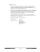
GROUND START POSITION LOOP START POSITION 8 9 COMMON 10 EARTH GROUND LINE SNIFFER SELECT Loop Start Ground Start TELCO CORD MODEL No. D161 RED Requires GROUND Optional Relay START Model No. D136 M Ground Start Jumper The ground start jumper is above the TELCO connector and TELTEST point at the lower left corner of the panel. Set it in the ground start position. See Figure 9.
Primary Phone Lines, Primary Phone Numbers Don’t confuse primary phone lines with primary phone numbers: With the D128 Dual Phone Line Switcher installed, the D9112 uses two phone lines, primary and secondary, to dial up to four phone numbers. These four phone numbers are designated as primary, backup, or duplicate. See Phone Routing in the Panel Wide Parameters module of the D9112 Program Entry Guide (7406145-000) for a description of these designations.
D128 Status LEDs Four LEDs mounted on the front edge of the D128 module show the status of AC power for the D9112, the status of the two phone lines, and communication failure. See Figure 10. AC Power LED The green AC power status LED lights when there is AC power at terminals 1 and 2 on the D9112 panel. Primary Fail LED The yellow Primary Fail LED lights when the D9112’s phone line monitor determines the primary phone line is faulted.
On-Board Points Description Terminals 11 to 22 The D9112 panel provides eight on-board points. Each point functions independently and does not interfere with the operation of the others. The panel monitors the sensor loops for normal, shorted, or open conditions between an input terminal (11, 13, 14, 16, 17, 19, 20, or 22) and any of the point common terminals (12, 15, 18, and 21). Programming for the point determines how the panel responds to those conditions.
Point Parameters You can determine the condition of on-board points 1 to 8 by measuring the voltage across the point input terminal and one of the common terminals. The sensor loops must be connected and the 1k ý end of line resistor in place. Open Loop = Greater than 3.7 VDC, but less than 5.0 VDC. Normal Loop = Greater than 2.0 VDC, but less than 3.0 VDC. Shorted Loop = Greater than 0.0 VDC, but less than 1.3 VDC.
Off-Board Points Point (ZONEX) Buss Terminals 23 to 28 You can use POPIT (Point of Protection Input Transponder) modules to provide up to 126 off-board points, bringing the total number of points the D9112 can monitor to 134. Each off-board point requires a POPIT module. POPITs connect to supervised two-wire data expansion loops run from POPIT to POPIT throughout the premises. Data expansion loops connect to a D8125 POPEX (Point of Protection Expander) module.
Listings The D8125 POPEX and D8127 POPIT modules are UL listed for Local or Police Connected Burglar Alarm, Central Station Burglar Alarm, Household Burglar Alarm, Central Station Fire (NFPA 71), Local Fire (NFPA 72, Chapter 6), Remote Station Fire (NFPA 72, Chapter 8), Household Fire (NFPA 74) and Electrically Actuated Transmitter Applications. See the Installation Guide for UL and Fire Applications in this manual to determine the required equipment and enclosures for your application.
Wiring the D8125 to the D9112 (Continued) Do not connect more than one D8125 to ZONEX 1, terminals 27 and 28, or ZONEX 2, terminals 25 and 26. See Wiring POPITs to the D8125 for instructions on connecting POPITs to the D8125 POPEX module.
Wiring POPITs to the Data Expansion Loop You can connect up to 63 POPITs to each D8125 module. Use one 2-wire data expansion loop or distribute the POPITs on up to three loops. Setting DIP switches on the POPIT modules assigns them to point numbers. See POPIT Module Point Assignments. Review Premises Wiring in the Installation section of this manual to determine if shielded wire is required. Determine the required wire gauge for each data expansion loop using Table 1.
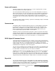
SWITCHES 1 TO 6 D8125 POPEX MODULE POINTS 9 - 71 (-) (-) (+) (+) GND OUT IN AUX D8127 POPIT DATA (-)(+) LOOP 33K Ω E.O.L. RESISITOR DATA (-)(+) LOOP DATA (-)(+) LOOP DATA (-)(+) LOOP NEGATIVE (-) POSITIVE (+) DATA EXPANSION LOOP UP TO 63 POPITS SWITCHES 1 TO 6 D8125 POPEX MODULE POINTS 73 - 135 (-) (-) (+) (+) GND OUT IN AUX DATA (-)(+) LOOP 33K Ω E.O.L.
Figure 14: D9112 Program Record Sheet Point Assignments Six switches on each POPIT assign the module to a point number. POPIT switch settings are found in the Point Assignment section of the D9112 Program Sheet. See Figure 14. D9112 Program Record Sheet The first column on the program record sheet contains the switch settings for the POPITs. Switches are numbered 1 to 6, left to right. Set switches whose number appears in the setting to the ON position.
POPIT Labels Off-board points are numbered 9 to 71 and 73 to 135. The D9112 reserves points 72 and 136 for internal use. You must connect POPITs for points 73 to 135 to expansion loops connected to POPEX #2. Four sheets of peel-off POPIT labels are supplied with the D8125 POPEX module. Use the sheet marked Vertical Grid for POPEX #1 for points 9 to 71 . Use the sheet marked Vertical Grid for POPEX #2 for points 73 to 135. Each label has two parts.
D8128A OctoPOPIT Module Description The D8128A OctoPOPIT Module combines the functions of the D8125 POPEX module and the D8127 POPIT modules to provide eight off-board points in a single module. You can use OctoPOPIT and D8125 POPEX modules on the same D9112. Warning, Do not use D8128 modules, they are not compatible with the D9112, only use D8128A modules: Using D8128 modules may cause intermittent missing and restoral reports. Be sure to only use D8128A modules.
Wiring OctoPOPITs to the D9112 Follow the procedure below to wire D8128A OctoPOPIT Modules to the D9112. You can connect OctoPOPIT and POPEX modules to the same Point Buss terminals. The modules wire in parallel. Remember you can never assign the same point number to more than one point. 1. Power down first: Power down the D9112 by disconnecting the positive (red) battery lead at the battery and unplugging the transformer. 2. Connect terminal 1 on the OctoPOPIT to terminal 23 on the D9112.
Line Termination If there is no D8125 POPEX module connected to ZONEX 1, terminals 27 and 28, set switch 12 on only one OctoPOPIT connected to those terminals to the on position. If there is a D8125 POPEX module connected to ZONEX 1, terminals 27 and 28, set switch 12 on all OctoPOPITs connected to those terminals to the off position. If there is no D8125 POPEX module connected to ZONEX 2, terminals 26 and 25, set switch 12 on only one OctoPOPIT connected to those terminals to the on position.
OctoPOPIT Sensor Loops The number normally-open and/or normally-closed detection devices each sensor loop can supervise is limited only by the resistance on the loop. Resistance on each sensor loop must be less than 100ý with the detection devices connected. Certain UL and NFPA applications may limit the number of detection devices. Consult the appropriate UL or NFPA standards.
Table 2: D8128A OctoPOPIT Switch Settings D8128A Switches 9 10 11 On On On On On Off On Off Off On Off On Off Off NCI #215 74-06144-000-C 2/96 D9112 Point # to ZONEX 1 D9112 Point # Connect D8128A to ZONEX 2 On P1 P2 P3 P4 P5 P6 P7 P8 9 10 11 12 13 14 15 16 73 74 75 76 77 78 79 80 Off P1 P2 P3 P4 P5 P6 P7 P8 17 18 19 20 21 22 23 24 81 82 83 84 85 86 87 88 On P1 P2 P3 P4 P5 P6 P7 P8 25 26 27 28 29 30 31 32 89 90 91 92 93 94 95 96 Off P1 P2 P3 P4 P5 P6 P7 P8 33 34 35 36 37 38 39 40
Testing Off-board Points Use the Service Walk Test item from the command center Service Menu to test off-board points. See the Service Walk Test in the Troubleshooting section of this manual for instructions. Walk test does not show extra points: Only the Service Walk Test shows extra points. If you incorrectly set the point assignment switches on a POPIT or OctoPOPIT, you may create both missing and extra points.
Off-board Relays D8129 OctoRelay The D8129 OctoRelay allows you to add relay outputs to your system in groups of eight. Up to 128 OctoRelay outputs (relay numbers 1 to 128) can be added to your system using 16 OctoRelays. Review the Power Outputs section of this manual to be sure you provide enough power for the OctoRelays and other powered devices you wish to connect to your system. OctoRelays for relay numbers 1 - 64 connect to ZONEX 1, terminal 28 on the D9112.
D9112 Relay Number D8129 OctoRelay On D9112, connect Switch Setting D8129 to 1 to 8 Off-On-On-On-On ZONEX 1 Terminal 28 9 to 16 On- Off-On-On-On ZONEX 1 Terminal 28 17 to 24 Off- Off-On-On-On ZONEX 1 Terminal 28 25 to 32 On- On-Off-On-On ZONEX 1 Terminal 28 33 to 40 Off- On-Off-On-On ZONEX 1 Terminal 28 41 to 48 On- Off-Off-On-On ZONEX 1 Terminal 28 49 to 56 Off- Off-Off-On-On ZONEX 1 Terminal 28 57 to 64 On- On-On-Off-On ZONEX 1 Terminal 28 65 to 72 Off-On-On-On-On ZONEX 2 Termi
Installation Do not use the instructions packaged with the D8129: They do not include instructions for connecting the module to the D9112 panel. Follow the instructions below. Set the switches on the OctoRelay before you install it in the enclosure. See Configuring the D8129 OctoRelay. You can install the OctoRelay in the enclosure with the D9112 (see Figure 2) or in an adjacent enclosure not more than 5 feet from the D9112. Use 16 to 22 AWG wire.
D811 Arm Status Relay Module The 811 Arm Status Relay Module allows you to add a single off-board relay output to your system. When used with the D9112 you can assign alarm output, auxiliary relay, sensor reset, arming status, point status, alarm memory, or remote functions (Command 54) to the D811 relay output. You are not restricted to the arming status mode only.
Wiring Connections Power down the panel to connect D811 modules as shown in Figure 18. Note that the D811 for relay number 53 connects to ZONEX 1 on the D9112. The D811 for relay number 117 connects to ZONEX 2 on the D9112.
Arming Devices Description Command centers, maintained or momentary contact keyswitches, or a combination of the two are used to arm and disarm areas. The D9112 panel may contain up to 8 areas. See the Introduction section for a description of areas. D1255 Command Centers Terminals 29 to 32 The Radionics D1255 Command Center is a 4-wire powered device used to arm and disarm areas, annunciate complete system status, initiate system tests, and control many functions of the D9112 security system.
Installation Consult the D1255 Installation Instructions (74-06819-000) for installation and mounting instructions. Command centers connect to the D9112 panel in parallel as shown in Table 5.
D9112 Charging And Programming D8132 RIPHERAL DEVICE CONNECTIONS ED LLOW POWER + 32 +12VDC DATA BUS A 31 DATA EEN DATA BUS B 30 ACK COMMON 29 F.P.A. yle 0.5 +12VDC COMMON DATA COMMON 28 Figure 19: Power at Command Centers D268/D269 Independent Zone Control D279 Independent Zone Control You can program any on-board or OctoPOPIT point so that the D268/D269 or D279 Independent Zone Control operates as independent point control (arms and disarms the point).
Keyswitch Description You can connect a maintained or momentary contact arming station (keyswitch) to master arm/disarm any of the areas in the D9112. The keyswitch is connected to an onboard or off-board point’s sensor loop. Relays can be programmed to activate arming status LEDs for keyswitch arming stations. See the Relays section of the D9112 Program Entry Guide (74-06145-000).
Programmer and Accessory Connections Programmer Connector (J7) The procedure below shows you how to connect and disconnect the programmer. Refer to D5200 Programmer Operation Manual (74-06176-000) for complete information on using the D5200 programmer. 1. Panel is operational during programming: Except when the programmer is sending or receiving, the D9112 is functional while the programmer is connected to it. It will transmit reports as programmed.
5. Disconnect the programmer. 6. Changes to some program parameters require a reset before they become effective. Reset Recommended: Radionics recommends that you reset the panel after changing program parameters with the D5200 programmer. If you locked down the reset pin in step 1, release it now to reset the panel. If you didn't lock the rest pin, momentarily close it now to reset the panel. See Figure 21.
74-06144-000-C 2/96 FACEPLATE SHIELD HOOKS 17-05823-002 D9112 LEDs Off When Normal YEL OPERATION MONITOR LED GRN Low Battery RED Reset Pin Disable All Except Battery Charging And Programming RESET PIN Reference Manual #74-06144-000 For System Wiring Diagram, Issue A Reference Manual #73-06143-000 For Compatible Smoke Detectors CLASS 2 TRANSFORMER 16.5 VAC 40 VA 60 HZ Part No.
Quick Reference Terminal Description Terminal 1, 2 Name CLASS 2 Description Connect 16.5 VAC, 40 VA transformer for primary power supply.
Installation Guide for UL and Fire Applications Listings and Approvals Fire UL Underwriters Laboratories lists the D9112 Control/Communicator as a Signal System Control Unit for: Central Station, Local, Auxiliary, Remote Station, and Household Fire Warning. CSFM Approved by the California State Fire Marshal. NYC-MEA Approved by New York City's Materials and Equipment Acceptance System. Factory Mutual (FM) Submitted for evaluation by Factory Mutual.
Introduction The D9112 System Chart references components evaluated and listed by Underwriters’ Laboratories for compatibility with the D9112 Control/Communicator. These components meet the basic system requirements for the applicable standard. The System Wiring Diagram, Issue A shows the relationship between the D9112 panel and the accessory components referred to in the D9112 System Chart.
Fire Applications (Continued) Enclosures Radionics offers three optional enclosures for the D9112. • The D8103 enclosure is suitable for residential fire and/or burglary installations and commercial burglary applications that do not require attack resistance or approval by Factory Mutual or NYC-MEA. (See the D9112 System Chart for acceptable applications.) • The D8108A is attack resistant.
D8109 Enclosure No Opt. D129 Class A Initiating Module # # # # Electrically Actuated Transmitter Central Station Fire Central Station Fire / Burglary Combined Local and Central Station Fire / Burglary (Grade C) Local and Central Station Fire Combined Req. Choose Req. one No No Req. No Calculate current draw to determine if second battery is required.
74-06144-000-C 2/96 D126 BATTERY 12V 7Ah + - AUX PWR ALARM TRIG COM SUPV IN ALARM CKT D192A P S ECL DEVICE 15-03130-001 S P + D126 BATTERY 12V 7Ah - + S P P P S S D9112 Operation & Installation Manual Page 65 S P - + - + D125 S P 1 10 3 4 2 or 5 MODEL No.
Current Rating Chart for Standby Battery Calculations AC Power On Normal Current AC Power Off Minimum Current In Alarm Maximum Current Each Unit Each Unit Each Unit Model Number Number Used D9112 ____ 250 x 1 = 250 250 x 1 = 250 500 x 1 = 500 D125B ____ 20 X Quan.= ____ 19 x Quan.= ____ 123 x Quan.= ____ D127 ____ 13 x Quan.= ____ 12 x Quan.= ____ 45 x Quan.= ____ D128 ____ 14 x Quan.= ____ 14 x Quan.= ____ 45 x Quan.= ____ D129 ____ 25 x Quan.= ____ 25 x Quan.
Standby Battery Requirements Household Burglary and Commercial Burglary Four hours of standby battery capacity required. Central Station or Local Fire Alarm 24 hours of standby plus 5 minutes of alarm operation required. See Central Station or Local Systems Ampere-Hour Calculation Formula in the Standby Battery Calculation for NFPA 72 Fire Alarm Applications section. Remote Station or Auxiliary Fire Alarm 60 hours of standby plus 5 minutes of alarm operation required.
Standby Battery Calculation for NFPA 72 Fire Alarm Applications Current Chart First See the D9112 Standby Battery and Current Rating Chart for totals B and C used in the formulas below. When connecting two batteries, use either the D122 Dual Battery Wiring Harness or the D8132 Battery Charger Module. The D8109 enclosure is required for all commercial fire applications. The D8108A enclosure is required for fire/burglary applications with a local bell.
Remote Station or Auxiliary Systems Remote Station or Auxiliary Systems require 60 hours of standby plus 5 minutes of alarm operation at the end of the 60 hour period. A D8132 Battery Charger Module with additional batteries installed in a separate D8109 or D8108A enclosure may be required in the D9112 system to meet the basic standby requirements for a Remote Station or Auxiliary System installation. You must use battery ampere hour (Ah) calculations to verify compliance.
Troubleshooting Guide Introduction Radionics provides this guide to help you troubleshoot problems with the D9112. To prevent problems from occurring, read the preceding sections of this manual and the program entry guide to verify that the panel is correctly installed and programmed. Self Diagnostics The D9112 performs a series of self diagnostic tests of its hardware, software, and program at start up and reset.
SERVC AC FAIL - AC Power Failed An interruption of AC Power at terminals 1 and 2 causes SERVC AC FAIL to appear in command center displays. You can program the panel to send an AC FAILED report to the receiver. Pressing CMD 4 silences the buzzer. Restoring power clears the display. SERVC BATT LOW - Battery Voltage Low If battery voltage at terminals 4 and 5 falls below 12.1 VDC, a SERVC BATT LOW appears in command center displays.
Phone Line Trouble Phone line problems that are not corrected can result in the D9112 going into Communications Failure. You can program the D9112 to monitor one or two phone lines. See the D9112 Program Entry Guide (74-06145-000) for programming instructions. If you enable the phone line monitor, SERVC PHONE LINE #1 (or 2 if two lines are used) appears in the command center’s display when the D9112 detects a problem on the phone line.
Communications Failure The D9112 goes into Communications Failure after ten unsuccessful attempts to reach the receiver. Follow the Phone Line Trouble procedure to verify that there is no problem with the phone lines at the D9112 installation. If the phone lines are good, monitor the lines (preferably at the receiver) for the symptoms listed below. Symptom The line rings but the D6500 receiver does not pick up. Diagnosis Line is not ringing at the receiver. Remedy 1.
Communications Failure (Continued) Symptom The receiver answers the call and provides an initial “handshake” acknowledgment, but does not acknowledge the D9112's report transmission with a “kiss-off” acknowledgment . Diagnosis The receiver is not compatible with the D9112's transmission format. Remedy Verify that the receiver is compatible with the format the D9112 is using (either BFSK or Modem II). SeePhone in the D9112 Program Entry Guide (74-06145-000).
Problems with Points If you incorrectly set the switches on a POPIT you may create both a missing and extra point. When you find a missing point, perform a Service Walk Test to search for extra points. See the Security System Owner’s Manual (71-06633-000) for test instructions. Symptom Point appears as missing at command centers and in reports to the receiver. Diagnosis POPIT is not connected or incorrectly connected to the data expansion loop.
Problems with Points (Continued) Symptom One or more points remain in trouble or alarm with all devices connected to the sensor loops normal. Faulted points do not generate alarms or troubles as programmed. Panel transmitts PT BUS TROUBLE reports. Erroneous alarm and/or trouble reports may follow PT BUS TROUBLE report. Erroneous alarm and/or trouble events for off-board points appear at command centers. NCI #215 74-06144-000-C 2/96 Diagnosis The sensor loop is open, shorted, or grounded.
Problems with Points (Continued) Symptom All off-board points are MISSING. Diagnosis Short on Aux Power, terminal 3 or ZONEX power, terminal 24. Remedy Terminals 3 and 24 share a common circuit breaker. Check wiring and devices connected to these terminals for shorts or grounds. If only one POPEX Check POPEX module for correct connections module is connected to the D9112 and the Data Expansion Loop.
Problems with the D8125 POPEX Data Expansion Loops EMI (Electro-magnetic Interference), excessive resistance, or intermittent grounds, shorts, or opens on the data expansion loop can cause erratic or intermittent functioning of points. Follow the procedures below to find the source of problems on the data expansion loop. EMI If you suspect EMI may be a problem, see EMI on Long Wire Runs in this section. AC induction on the data expansion loops must be less than 10 VAC.
Checking Shielded Cable If improperly installed, shielded cable can create problems rather than solve them. Follow the procedure below to check shielded cable for proper installation. 1. Remove the drain wire for the shield from terminal 10. 2. Meter the drain wire for continuity to terminal 10 (earth ground). If there is continuity, find and remove the foreign ground on the drain wire. 3. Reconnect the drain wire to terminal 10. 4.
Problems with Command Centers Symptom Diagnosis Command centers A supervised address show erratic behavior. has been entered in more than one For example, the pip command center. that confirms you pressed a key "echoes" or the back lighting flashes off and on. One or more of the keys is stuck under the faceplate NCI #1, #40 NO AUTHORITY displays at command center when you enter your passcode to perform a function.
Battery and Power Reports You can program the D9112 to transmit both battery and AC power status reports. See the D9112 Program Entry Guide (74-06145-000). If battery or AC power reports are a problem check the following. 1. Check to be sure you are not overloading the D9112's power supply. Review the Power Outputs section and Overloaded Power Supply in this section. 2. Verify that there is at least 16.5 VAC on terminals 1 and 2. 3.
Overloaded Power Supply If the load on the D9112's power supply exceeds it's capacity, the panel follows a routine to protect itself and the battery. It sends reports to the receiver at several points during this routine. Keep in mind that AC power remains at terminals 1 and 2 as you read the overload scenario below. 74-06144-000-C 2/96 • The panel is operating normally with a good battery, AC is present at terminals 1 and 2, and auxiliary power load is under 1.4A.
Service Walk Test The Service Walk Test differs from the standard Walk Test in that POPITs whose switches are set for a point number not programmed in the panel appear in the test. Service Walk Test only available at command centers with panel wide scope: See Command Center in the D9112 Control/Communicator Program Entry Guide (74-06145000) for a description of command center scope.
SERVICE WALK ? ENT 134 PTS TO TEST Test a device POINT TEXT (Text displays 60 seconds) 133 PTS TO TEST Test a device POINT TEXT ESC (Text displays 60 seconds) 132 PTS TO TEST Test a device POINT TEXT 1 PTS TO TEST Test a device 0 PTS TO TEST ESC IDLE TEXT VIEW UNTESTED ? ENT ESC # PTS UNTESTED ESC NEXT POINT TEXT Figure 23: Service Walk Test Flow Chart 74-06144-000-C 2/96 D9112 Operation & Installation Manual Page 84 © 1993-1996 Radionics
Command 5 7 Toggles Default Idle Text Command 5 7 allows technicians who might not be familiar with the custom idle text to confirm whether an area is armed or ready to arm. The default idle text displays are: AREA # IS ON AREA # IS OFF Follow the procedure below to toggle between custom and default idle text. 1. Ensure the command center is at idle text. 2. Press COMMAND 5 7. 3. The display will change to default idle text for 5 seconds and then revert to its original idle text.
Specifications Voltage Input Primary Power Supply 1 2 16.5 VAC 40 VA class 2 plug-in transformer (D1640) Secondary Power Supply 4 5 12 VDC 7 Ah sealed lead acid rechargeable battery. The D9112 supports a maximum of two 12 VDC 7 Ah batteries using the D122 Dual Battery Harness. Current Requirements Panel - 500 mA See the D9112 Standby Battery and Current Rating Chart for the current requirements of other system components.
SDI Bus Compatible Accessories SDI Bus A (+): 9 VDC (15,000' max) SDI Bus B (-): 9 VDC (15,000' max) Telephone Connections Connection RJ31X or RJ38X jack can be interfaced with the D9112. Two TelCo Lines Radionics D128 Dual Phone Line Module required for two phone line service. Supervision supplied by the panel. Environmental Temperature: 32°-122°F (0°-50°C) Relative Humidity: 5-85% at 86°F (30°C) non-condensing See the Radionics Product Catalog for complete list.