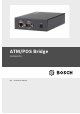
ATM/POS Bridge DVRXEAP01 en Installation Manual
ATM/POS Bridge Table of Contents | en 3 Table of Contents 1 Safety 5 1.1 FCC & ICES compliance 7 2 Description 9 2.1 Parts List 9 2.2 Supported Protocols 9 3 System Overview 10 4 Installation 11 4.1 Mounting the Bridge 11 4.2 Making Connections to the Bridge 12 4.3 COM Connector Detail 14 5 Configuration 15 5.1 Configuring the Bridge for a Network Connection 15 5.1.1 Using the Bridge Detector Utility 15 5.1.2 Using the Direct Connection 16 5.
en | Table of Contents ATM/POS Bridge 6 Configuration Using HyperTerminal 24 6.1 Connecting the Bridge 24 6.2 Initiating a HyperTerminal Session 24 6.3 Configuring Bridge Operation via HyperTerminal 26 6.3.1 Network Setup 26 6.3.2 Communication Channels 28 6.3.3 Terminal Setup 29 6.3.4 Simulation Mode 31 6.3.5 Recording Language 31 6.3.6 Service Menu 32 7 Troubleshooting 33 8 Technical Data 34 A Updating Bridge Firmware 36 F.01U.171.816 | 1.0 | 2010.
ATM/POS Bridge 1 Safety | en 5 Safety Type numbers: DANGER! High risk: This symbol indicates an imminently hazardous situation such as “Dangerous Voltage” inside the product. If not avoided, this will result in an electrical shock, serious bodily injury, or death. WARNING! Medium risk: Indicates a potentially hazardous situation. If not avoided, this could result in minor or moderate bodily injury. CAUTION! Low risk: Indicates a potentially hazardous situation.
en | Safety ATM/POS Bridge 7. Do not overload outlets and extension cords, as this can 8. Protect the plug and power cord from foot traffic or 9. Operate the unit only from the type of power source cause fire or electrical shock. pinching, at electrical outlets, and at its exit from the unit. indicated on the label. 10. Unless qualified, do not attempt to service a damaged unit yourself. Refer all servicing to qualified service personnel. 11.
ATM/POS Bridge 1.1 Safety | en 7 FCC & ICES compliance FCC & ICES Information (U.S.A. and Canadian Models Only) This equipment has been tested and found to comply with the limits for a Class B digital device, pursuant to part 15 of the FCC Rules. These limits are designed to provide reasonable protection against harmful interference in a residential installation.
en | Safety ATM/POS Bridge Informations FCC et ICES (modèles utilisés aux États-Unis et au Canada uniquement) Suite à différents tests, cet appareil s'est révélé conforme aux exigences imposées aux appareils numériques de classe B, en vertu de la section 15 du règlement de la Commission fédérale des communications des États-Unis (FCC), et en vertu de la norme ICES-003 d'Industrie Canada.
ATM/POS Bridge 2 Description | en 9 Description The ATM/POS Bridge provides an interface between a digital recorder and either Automatic Teller Machines (ATM) or Pointof-Sale (POS) equipment such as cash registers. Both singleand multi-drop ATM networks are supported. This allows financial transaction data to be recorded and linked to specific camera images. The bridge supports up to four (4) serial connections to directly connect devices to each ATM/POS bridge.
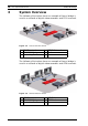
3 en | System Overview ATM/POS Bridge System Overview The following illustration shows an example of how a bridge is used in a network of digital video recorders and POS terminals. Figure 3.1 1 2 3 POS terminal network POS Terminal ATM/POS Bridge Recording Device 4 5 TCP/IP Network Printer The following illustration shows an example of how a bridge is used in a network of digital video recorders and ATM terminals. Figure 3.
ATM/POS Bridge 4 Installation | en 11 Installation This section details the physical installation of the ATM/POS Bridge. 4.1 Mounting the Bridge Determine a location where all incoming connections can reach the ATM/POS Bridge. Using the screws provided, attach the two mounting brackets to the sides of the bridge. Secure the brackets to a solid fixture. Bosch Security Systems, Inc. Installation Manual F.01U.171.816 | 1.0 | 2010.
en | Installation 4.2 ATM/POS Bridge Making Connections to the Bridge Use the following illustration to make the appropriate connections to the ATM/POS Bridge: Figure 4.1 1 2 3 4 5 6 7 ATM/POS Bridge connectors Ethernet RJ45 connector COM 3 RS-232 connector (console port) DC power input connector Activity indicator COM 4 RS485 connector COM 2 RS232 connector COM 1 RS232 connector F.01U.171.816 | 1.0 | 2010.09 Installation Manual Bosch Security Systems, Inc.
ATM/POS Bridge 1. Installation | en 13 Connect the supplied DC power adapter unit to the DC power input connector of the bridge. 2. Connect the RJ45 connector of the bridge via a straight Ethernet CAT5 network cable to a network switch or hub that supports 10BaseT. 3. Connect your terminal to COM ports 1, 2, 3, or 4 of the bridge using the supplied cable. Refer to Section 4.3 COM Connector Detail, page 14 for pin-out details.
en | Installation 4.3 ATM/POS Bridge COM Connector Detail The four COM connectors on the bridge are all 9-pin SubD-type male connectors. 1 5 6 Figure 4.2 Pin 9 COM connector detail COM 1 COM 2 COM 3 COM 4 RS232 RS232 (console) RS485 RS232 1 2 3 4 5 6 7 8 9 Rx Tx Rx Tx Rx Tx D2+ D2- GND GND GND GND RxC TxC RxC TxC INIT Note: The console cable has pin 9 connected to pin 5 (GND). When pin 9 of COM 3 (console) is at GND level on power-up, the bridge enters firmware download mode.
ATM/POS Bridge 5 Configuration | en 15 Configuration You must configure the ATM/POS Bridge network settings to ensure proper communication on an existing TCP/IP network. This section provides configuration details using the Web-based interface. To configure the bridge using a HyperTerminal session, refer to Section 6 Configuration Using HyperTerminal, page 24. For instructions to update the ATM/POS Bridge firmware, refer to Section A Updating Bridge Firmware, page 36. 5.
en | Configuration 3. ATM/POS Bridge From a PC connected to the same network, launch the BridgeDetector.exe application, located on the CD. The PC opens the Bridge Detector window that displays the MAC Address and the default IP Address, Subnet Mask, and Gateway for the bridge. 4. To change the network settings for the bridge, first select a bridge. Then, type a valid IP Address, Subnet Mask, and Gateway in the input boxes on the right side of the Bridge Detector window.
ATM/POS Bridge 5. Configuration | en 17 Launch Internet Explorer and navigate to the default bridge IP Address: 169.254.1.1 Internet Explorer displays the ATM/POS Bridge interface. 6. Click the Network Setup link in the navigation pane. 7. Type an optional name for the bridge in the Bridge Name input box. This name facilitates recognition of the bridge on the network. 8. To change the network settings for the bridge, type a valid IP Address, Subnet Mask, and Gateway in the appropriate input boxes.
en | Configuration 5.2 ATM/POS Bridge Configuring Operation via a Network After the bridge is properly configured for network access, you can configure the COM and Terminal settings via Internet Explorer. To access the bridge configuration page: 1. Launch Internet Explorer and navigate to the IP address for the bridge. Internet Explorer displays the ATM/POS Bridge interface. 2. Use the menu in the left pane to navigate to the various configuration pages. 3.
ATM/POS Bridge Configuration | en – Simulation Mode: Select the type of device to test the 19 connection between the bridge and the digital recorder. Select this mode to send sample data from the bridge to the digital recorder. – Recording Language: Select the language that is set on the digital recorder to ensure that characters display correctly. – Log Level: Ensure that the Log Level setting is None. This setting is used for diagnostic purposes only.
en | Configuration – ATM/POS Bridge Bridge Name: Type an optional name for the bridge in the Bridge Name input box. This name facilitates recognition of the bridge on the network. – IP Address: Displays the current IP Address for the bridge. You can type a new IP Address in the input box. – Subnet Mask: Displays the current Subnet Mask for the bridge. You can type a new Subnet Mask in the input box. – Default Gateway: Displays the current Gateway Address for the bridge.
ATM/POS Bridge 5.2.3 Configuration | en 21 Terminal The Terminal Setup pages allow you to configure the bridge to accept transactions from the ATM/POS devices connected to the bridge. – Name: Type an optional name for the terminal. This name facilitates recognition of the terminal on the network – Device: Select the type of POS or ATM device.
en | Configuration – ATM/POS Bridge Code Page: Select the code page (character set for a particular language) that the ATM/POS terminal uses to encode transaction data.
ATM/POS Bridge 5.2.4 Configuration | en 23 COM Port The COM Port page enables you to configure the four physical communication port settings on the bridge.
en | Configuration Using HyperTerminal 6 ATM/POS Bridge Configuration Using HyperTerminal You can configure the ATM/POS Bridge via a PC HyperTerminal session. The PC is connected to the COM 3 (console) port on the bridge via a serial connection. For instructions to update the ATM/POS Bridge firmware, refer to Section A Updating Bridge Firmware, page 36. 6.1 Connecting the Bridge 1. 2. Ensure that the bridge is connected to the power supply.
ATM/POS Bridge 4. Configuration Using HyperTerminal | en 25 Ensure that the settings in the COM Properties dialog box match these settings: 5. – Bits per second: 9600 – Data bits: 0 – Parity: None – Stop bits: 1 – Flow control: None Click OK to accept the COM properties and to start the HyperTerminal session. 6. Refer to Section 6.3 Configuring Bridge Operation via HyperTerminal, page 26 for details about configuring the bridge operation via HyperTerminal. Bosch Security Systems, Inc.
en | Configuration Using HyperTerminal 6.3 ATM/POS Bridge Configuring Bridge Operation via HyperTerminal After you establish a HyperTerminal connection between a PC and the bridge, use the menu structure to configure the bridge settings. Press the F1 key to open the System Options menu, then select 1 - Network Setup. 6.3.1 Network Setup The Network Setup enables you to provide a label for the bridge and to configure network settings.
ATM/POS Bridge – Configuration Using HyperTerminal | en 27 Bridge Name: Type an optional name for the bridge in the Bridge Name input box. This name facilitates recognition of the bridge on the network. – IP Address: Displays the current IP Address for the bridge. Select option 2 to enter a new IP Address. – Subnet Mask: Displays the current Subnet Mask for the bridge. Select option 3 to enter a new Subnet Mask. – Default Gateway: Displays the current Gateway Address for the bridge.
en | Configuration Using HyperTerminal 6.3.2 ATM/POS Bridge Communication Channels Select the Communication Channel option to configure the four physical communication port settings on the bridge. Select the appropriate option to configure a specific COM port.
ATM/POS Bridge 6.3.3 Configuration Using HyperTerminal | en 29 Terminal Setup The Terminal Setup pages allow you to configure the bridge to accept transactions from the devices connected to the bridge. Select a terminal number to configure the settings for that terminal. – Name: Select option 1 to type an optional name for the terminal. This name facilitates recognition of the terminal on the network – Device: Select the type of POS or ATM device.
en | Configuration Using HyperTerminal – ATM/POS Bridge Code Page: Select the code page (character set for a particular language) that the ATM/POS terminal uses to encode transaction data.
ATM/POS Bridge 6.3.4 Configuration Using HyperTerminal | en 31 Simulation Mode Use the Simulation Mode to select the type of device to test the connection between the bridge and the digital recorder. Select this mode to send sample data from the bridge to the digital recorder. This setting is set to Off for normal operation. 6.3.5 Recording Language Select the language that is set on the digital recorder to ensure that characters display correctly. Bosch Security Systems, Inc.
en | Configuration Using HyperTerminal 6.3.6 ATM/POS Bridge Service Menu The System Menu contains settings for bridge operation. – Restore Defaults: Resets all COM and Terminal settings to factory defaults. This button does not reset the Network settings. – Reset Bridge: Reboots the bridge by cycling the power. – Diagnostics: Select this option to perform the EEPROM diagnostic test. – Version Info: Displays the firmware release level for the bridge. F.01U.171.816 | 1.0 | 2010.
ATM/POS Bridge 7 Troubleshooting | en 33 Troubleshooting If you are unable to capture transaction data, follow these steps: 1. 2. Check all cable connections. Check the TCP/IP network connection with the ATM/POS Bridge. Ensure that the IP Address, Subnet Mask, and Gateway Address are valid and appropriate for the network. 3. If the recorder has established communication with your bridge and you cannot capture transaction data, use the simulation mode (refer to Section 5.2.
8 en | Technical Data ATM/POS Bridge Technical Data Electrical Power Supply External DC power supply (supplied) Input: 100–240 VAC, 150 mA, 50/60 Hz Output: 12 VDC, 450 mA Connector DC jack, positive center pin, 10–30 VDC, 2 W Mechanical Dimensions 152 x 110 x 35 mm (5.98 x 4.33 x 1.38 in.) Weight Approximately 0.6 kg (1.
ATM/POS Bridge EMC Technical Data | en 35 USA: FCC Part 15, Class B Requirements EU: EMC directive 89/336/EEC Immunity: EN50130-4 Emission: EN55022 Class B Harmonics: EN61000-3-2 Voltage Fluctuations: EN61000-3-3 Safety USA: UL60950 EU: EN60950 Canada: CAN/CSA - C22.2 - 60950-00 Bosch Security Systems, Inc. Installation Manual F.01U.171.816 | 1.0 | 2010.
A en | ATM/POS Bridge Updating Bridge Firmware Follow the steps below to update the firmware on the ATM/ POS Bridge. 1. Download the Zip file for the ATM/POS Bridge firmware from the Bosch Security Systems Web site (www.boschsecurity.com). 2. Unzip the firmware update file into a folder on the PC that 3. Run the downloadwizard.exe file to start the update you will use to update the bridge. process. The PC displays the initial wizard screen. 4.
ATM/POS Bridge | en a. Unplug the power cable from the bridge. b. Connect the supplied console cable to COM Port 3 37 (console) on the bridge and to a COM port on the PC. c. Connect the supplied power adapter to the bridge and to the main power. The red LED light on top of the bridge flashes short pulses to indicate that the bridge is in download mode.
en | ATM/POS Bridge 6. Click Next to select the download parameters. 7. Click the check boxes to download the Bridge Software and the Printer definition and simulation files. A check mark indicates that the process will update the specific files. 8. Select the folder where the firmware and printer definition files are stored. By default, the wizard searches for the file in the same directory that contains the downloadwizard.exe file. 9. To navigate to a different folder, click the ...
ATM/POS Bridge | en 39 10. Click Next to select the device profiles that are stored on the bridge. – Select individual check boxes to select specific device profiles. – Click the Select All Devices to select all device profiles. – Click Unselect All Devices to clear the check boxes for all device profiles. 11. Click Next to view a summary of the download settings and to start the update process. Bosch Security Systems, Inc. Installation Manual F.01U.171.816 | 1.0 | 2010.
en | ATM/POS Bridge 12. Click Finish to accept the settings and to start the firmware update. If you receive an error message, refer to Page 41. 13. Click Yes to overwrite the existing files on the bridge. The wizard displays a download progress screen. DO NOT interrupt the update process. 14. Click OK once the upload process is complete. 15. Disconnect the power cable and the console cable from COM Port 3 on the bridge. 16. Reconnect a serial cable from a terminal to COM Port 3, if required.
ATM/POS Bridge | en 41 Troubleshooting Bridge Firmware Update Use the following steps to correct the firmware settings If you receive the following error during the firmware update process: 1. Click OK to acknowledge the error. 2. Click the Cancel button to stop the process and to quite the wizard. 3. Re-launch the downloadwizard.exe file to start the update process. 4. Follow the process until you reach the communications setup wizard screen.
en | F.01U.171.816 | 1.0 | 2010.09 ATM/POS Bridge Installation Manual Bosch Security Systems, Inc.
Bosch Security Systems, Inc. www.boschsecurity.com © Bosch Security Systems, Inc.