SC3100 Operation and Installation Guide Radio Communicator
SC3100 90026-201D SC3100 Operation and Installation Guide Page 2 © 2004 Bosch Security Systems
SC3100 Contents 1.0 SAFECOM Telemetry Communications System ........................................................................ 5 1.1 1.2 1.3 1.4 1.5 1.5.1 1.5.2 1.5.3 1.6 1.6.1 1.6.2 1.6.3 1.6.4 1.6.5 SAFECOM Communications Paths .................................................................................................................. 5 Overview of SAFECOM Radio Communicators ...............................................................................................
SC3100 Contents Figures Figure 1: Figure 2: Figure 3: Figure 4: Figure 5: Figure 6: Figure 7: SAFECOM System................................................................................................................................................. 5 SC3100 Circuit Board........................................................................................................................................... 11 SC3100 Radio Communicator...................................................................
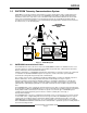
SC3100 Introduction 1.0 SAFECOM Telemetry Communications System SAFECOM is a long range telemetry communications system for monitoring life safety security alarm panels which are remotely located at a customer site. The SAFECOM system utilizes specially designed telemetry transmitters and receivers to provide a secure and reliable radio communications link between remote alarm panels and a Central Monitoring Station.
SC3100 Introduction The use of a SAFECOM type or equivalent repeater significantly increases the coverage area (range). Radio area coverage and reception ranges are also dependent on the extent of a number of environmental effects, e.g., propagation losses due to atmospheric conditions, and the proximity of the radio transmission and reception paths to dense foliage and metal structures. The majority of SAFECOM Radio Communicators are ordered to TX and RX in the 450-470 MHz UHF frequency range.
SC3100 Introduction 1.3 SC3100, Full Data Transfer, Radio Communicator The SC3100 Radio Communicator is a derivative of the capabilities and features found on the SAFECOM SC4000. The SC3100 and the SC4000 share the same two-way communications characteristics and receivingand-sending functions of host alarm panel signals. However, the SC3100 is a non-UL Listed device and is not configured with inputs or output relays.
SC3100 Introduction 1.4 SAFECOM SC3100 Radio Communicator Specifications • • • • • • • • Size: 4.5" W x 4.1 " H x 2.5" D (11.4 cm W x 10.4 cm H x 6.4 cm D) Weight: About 1 lb. (0.
SC3100 Introduction 1.6.4 Federal Communications Commission (FCC) Statement This equipment generates and uses radio frequency (RF) energy. If not installed and used properly, that is, in strict accordance with the manufacturer's instructions, it may cause interference to radio or television reception. This equipment has been tested and certified to comply with the specifications for a Class B digital device, pursuant to Subpart J of Part 15 of FCC rules.
SC3100 Introduction Notes: 90026-201D SC3100 Operation and Installation Guide Page 10 © 2004 Bosch Security Systems
SC3100 SC3100 Circuit Board 2.0 Circuit Board 2.1 SC3100 Circuit Board Components The following describes the function of the headers, LEDs, and some of the significant components located on the SC3100 Communications Panel circuit board.
SC3100 SC3100 Circuit Board JP1 - CPU Reset (Reboot) This allows system reset or initialization of the Central Processor Unit (CPU). Shorting the two pins on this header and cycling the system power will erase the program from the SC3100, making it operate as if it was a “new, out of the box” unit. Radio This header is to connect the interface cable from the internal RA500 Radio Module to the radio adapter board inside the SC3100.
SC3100 SC3100 Circuit Board The battery restore message will NOT be sent by the SC3100 until the charge on the SC3100 Battery has reached a minimum of 11.5 VDC during transmit TX ACTIVE. Note: The SC3100 battery voltage is only tested when the radio transceiver is transmitting. Note: The SC3100 internal battery is shipped from Bosch Security Systems disconnected. The installer MUST open the SC3100 enclosure and connect the internal battery connector.
SC3100 SC3100 Circuit Board Notes: 90026-201D SC3100 Operation and Installation Guide Page 14 © 2004 Bosch Security Systems
SC3100 Pre-Installation Requirements 3.0 Pre-Installation Requirements 3.1 SC3100 Pre-Installation Requirements Prior to the installation of the SC3100 Radio Communicator, several conditions must be satisfied and physical phenomena considered to insure trouble free operation. 3.2 SC3100 Wiring Requirements All wiring utilized for the installation of the host alarm panel and the SC3100 Radio Communicator shall be in accordance with local building codes.
SC3100 Pre-Installation Requirements 3.5 SC3100 Radio Communicator Location The SC3100 Radio Communicator is designed to be installed inside of the host alarm panel. If the size of the host alarm panel will not permit mounting the SC3100 inside or for special SC3100 configurations, then the SC3100 enclosure can be mounted directly to a vertical surface, like a wall, using the keyhole mounting holes provided on the rear of the SC3100 enclosure.
SC3100 Pre-Installation Requirements IMPORTANT All sales personnel must be required to utilize the IT1500 Tester with a minimum of 9dB attenuator installed between the IT1500 Tester and the Tester Antenna to determine if two-way radio communication between the prospective customer site and the Central Station SC9000 computer is possible before the job is sold.
SC3100 Pre-Installation Requirements Notes: 90026-201D SC3100 Operation and Installation Guide Page 18 © 2004 Bosch Security Systems
SC3100 Installation 4.0 Installation Procedures This section describes the installation procedures for the SC3100 Radio Communicator. 4.1 SC3100 Radio Communicator Mount the SC3100 at the location determined from the considerations discussed in Section 3.0. The total weight of the SC3100 is about one pound (0.5 kg) with the internal 12 VDC battery installed. The SC3100 is normally installed in an upright position in the bottom and inside of the host alarm panel enclosure (see Figure 3).
SC3100 Installation The RF bulkhead connector, on the end of the factory supplied coaxial cable, may be installed directly on the host alarm panel enclosure by using one of the following methods: 1. An existing knock-out port (on the top of the host alarm panel enclosure). 2. A ½ in. diameter hole, carefully drilled into the top of the host alarm panel enclosure. 3. The 2" x 2" factory supplied antenna mounting L-Bracket (P/N 80072-101). Use the 1.
SC3100 System Initialization 5.0 System Initialization The following describes the System Initialization Procedures for the SC3100 Radio communicator. 5.1 System Initialization Procedures Contact the Central Station SAFECOM computer operator. Then verify that the following information is entered in the SAFECOM SC9000 computer account for the specific SC3100 you are working on.
SC3100 System Initialization The following illustrates the second setup menu in the SC9000 computer for programming an SC3100 account. Below is a summary of the parameters necessary to complete the programming of an SC3100 account into the SAFECOM computer. This is the second setup menu. These parameters must be entered, then the operator will escape out and save the data to complete the building of the account.
SC3100 System Initialization Note: For older SC3100s, the programming version required the operator to set two parameters, “Dialer ACK” and “Dialer Format” as shown below. “Dialer ACK”: 0= Short burst 2300 Hz, short burst 1400 Hz, long burst 2300 Hz, long burst 1400Hz. 1= Short burst 2300 Hz, short burst 2300 Hz. 2= Short burst 1400 Hz, short burst 1400 Hz. 3= Long burst 2300 Hz, long burst 2300 Hz. 4= Long burst 1400 Hz, long burst 1400 Hz. 5= DTMF (ADEMCO Contact ID / 4+2 Express / High Speed).
SC3100 System Initialization 30= Long 2300 Hz ACK Tone, Any digital pulse type format. 31= Long 2300 Hz ACK Tone, Radionics BFSK. 32= Long 2300 Hz ACK Tone, 0-2 pulse type format. 33= Long 2300 Hz ACK Tone, 0-2 pulse type format with parity. 34= Long 2300 Hz ACK Tone, 3+1 pulse type format 35= Long 2300 Hz ACK Tone, 3+1 pulse type format with parity. 36= Long 2300 Hz ACK Tone, 4+2 pulse type format 37= Long 2300 Hz ACK Tone, 4+2 pulse type format with parity.
SC3100 System Initialization red. The number of blinks indicates a specific type of hardware failure. The blinking cycle will continue until the auxiliary power source is removed from the SC3100. The following describes the red blinking behavior of the System Status LED during a hardware failure, and should not be confused with System Status green LED illumination during normal SC3100 operations: • 1 blink red, pause, then repeat: Bad ROM check sum. 5.
SC3100 System Initialization Notes: 90026-201D SC3100 Operation and Installation Guide Page 26 © 2004 Bosch Security Systems
SC3100 6.
SC3100 Programming Worksheet Notes: 90026-201D SC3100 Operation and Installation Guide Page 28 © 2004 Bosch Security Systems
SC3100 Warranty 7.0 Limited Warranty Warranty Coverage and Duration Bosch Security Systems warrants to the original purchaser its Bosch Security Systems manufactured “SAFECOM" products ("Product") against defects in material and workmanship under normal use and service for a period of one year from the date of purchase.
SC3100 Notes 90026-201D SC3100 Operation and Installation Guide Page 30 © 2004 Bosch Security Systems
SC3100 Notes © 2004 Bosch Security Systems SC3100 Operation and Installation Guide Page 31 90026-201D
© 2004 Bosch Security Systems 130 Perinton Parkway, Fairport, NY 14450-9199 Customer Service: (800) 289-0096 Technical Support: (888) 886-6189 90026-201D Operation and Installation Guide 03/04 SC3100 Page 32 of 32