DISHWASHER Installation Instructions LAVE-VAISSELLE Instructions d’installation LAVADORA DE PLATOS Instrucciones de instalación ! " # "" SHI66A, SHU33A, SHU43C, SHU53A, SHU66C, SHU43E, SHU53E, SHU66E, SHV46C, SHV66A, SHX33A, SHX46A, SHX46B, SHX56B, SHY56A, SHY66C $
INTRODUCTION .................................................. .2 TOOLS AND MATERIALS NEEDED ......................... .3 MATERIALS SUPPLIED .......................................... .4 CHOOSING LOCATION ......................................... .5 PLUMBING PREPARATION .................................... .6 ELECTRICAL PREPARATION .................................. .7 PLACING THE DISHWASHER ................................ .8 DRAIN HOSE CONNECTION ................................. .
INTRODUCTION THESE INSTALLATION INSTRUCTIONS ARE INTENDED FOR USE BY QUALIFIED INSTALLERS. In addition to these instructions the dishwasher shall be installed: • • In the United States, in accordance with the National Electric Code/State and Municipal codes and/or local codes. In Canada, in accordance with the Canadian Electric Code C22.1 -latest edition/Provincial and Municipal codes and/or local codes. Please read these installation instructions completely and carefully.
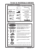
TOOLS & MATERIALS NEEDED Tools Needed for Installation ! " # $ % & % + ' ( ' ENGLISH " & % $$ ) * Figure 1 Materials Needed Electric Connection - 2 conductor, 1 ground insulated electrical supply cable (30” or sufficient length for your installation). Hot Water Supply Line - Minimum 3/8” O.D.
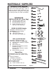
MATERIALS SUPPLIED Accessory Parts Supplied Accessory Parts for your model dishwasher will come in one or more plastic bags. Check to make sure that the parts supplied for your model are all there. See Figure 3. If any parts are missing contact your dealer immediately. DISHWASHER INSTALLATION KIT (Clear Bag) D. E. F. G.
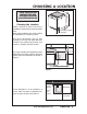
CHOOSING A LOCATION 3-1/2” (90mm) Choosing the Location 1-15/16” (49mm) 4” (102mm) Figure 4 Any built-in dishwasher must be fully enclosed on the top, both sides and back. Therefore the cabinet space below your counter is probably the best location. 23-9/16” (598 mm) For proper operation and appearance of the dishwasher, the cabinet opening should be square and have dimensions as shown in Figure 5.
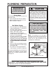
PLUMBING PREPARATION THESE INSTALLATION INSTRUCTIONS ARE INTENDED FOR USE BY QUALIFIED INSTALLERS Drain Hose The dishwasher comes with a seven (7) foot drain hose. • A 1.25” access hole must be made to allow the drain hose to be run to the drain connection location. CAUTION To protect against possible rupture of the fill valve, water lines leading to the dishwasher, as well as water lines in the dishwasher MUST be protected against freezing. If the valve or water line freezes, flooding may occur.
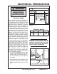
ELECTRICAL PREPARATION WARNING 23-5/8”-24-1/8” (600-613mm) 3-1/2 (90 mm) Electrical Supply The customer has the responsibility to ensure that the dishwasher installation is in compliance with all national and local electrical codes and ordinances. The dishwasher shall be installed by a qualified electrician and properly grounded. The electrical supply for which the dishwasher is designed is 120V, 60 Hz, AC, connected to a dishwasher-dedicated electrical circuit with a fuse or breaker rated for 15 amps.
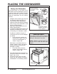
PLACING THE DISHWASHER Placing the Dishwasher The profile strips on the sides of the dishwasher allow the dishwasher to fit into a cabinet opening with a width of 23-5/8” (600 mm) to 24-1/8” (613 mm). Before sliding the dishwasher into the cabinet opening: • • • • • Straighten the hot water supply line and the electrical cable (see Figure 11). Level & Align (initial adjustments). Guide the drain hose carefully (avoiding kinks in hose) as the dishwasher is slid into the cabinet opening.
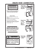
DRAIN HOSE CONNECTION Drain Hose in Sink with Air Gap/ No Disposer Rubber Connector min. 20” (500 mm) clearance to floor Be sure to follow your national and local codes at all times. Air Gap Drain Hose Trap ENGLISH THESE INSTALLATION INSTRUCTIONS ARE INTENDED FOR USE BY QUALIFIED INSTALLERS Figure 12 Air Gap Drain Hose in Sink with Air Gap & Disposer min. 20” (500 mm) clearance to floor • Before beginning, turn off the water supply! • The access hole for the drain hose should be 1.
HOT WATER CONNECTION THESE INSTALLATION INSTRUCTIONS ARE INTENDED FOR USE BY QUALIFIED INSTALLERS Shut off valve (not included) Connecting the Hot Water Supply Line • If using a solder joint instead of a compression fitting, be sure to make all solder connections before connecting the water line to the dishwasher. • Make sure there are no sharp bends or kinks in the water line which might restrict water flow. • When connecting threaded pipe use pipe thread compound or Teflon tape to seal the connection.
ELECTRICAL SUPPLY CONNECTION Connecting Electrical Supply Be sure to follow all local and national electrical codes and ordinances. • Install strain relief or conduit connector into opening on power supply box. • Strip the insulated wires, being extremely careful not to strip too much insulation. • Insert and securely fasten into strain relief, two-conductor supply cable with ground. • Twist wire connectors tightly onto the wires, ensuring that no bare wiring is exposed (from insulated wires).
DOOR PANEL INSTALLATION Accessory Panel Installation SHU Models If you have an SHU model and have ordered an accessory panel kit it must be installed prior to sliding the dishwasher into place. Dimensions of panel size that may be used is shown in Figure 19. Panel Installation, SHV Models If you have an SHV model, a fully integrated model, you will have additional mounting hardware and a folded template sheet with installation instructions comprised of pictograms.
DOOR PANEL INSTALLATION 25” (636 mm) ENGLISH SEE FOLDED PANEL INSTALLATION TEMPLATE SHEET FOR STEP BY STEP INSTRUCTIONS ON HOW TO INSTALL YOUR DISHWASHER PANEL(S). 1/4” max. (6 mm) 23-1/16” (586 mm) Figure 19 IMPORTANT Do NOT Drill Completely through your custom door panel. EXTENSION "A" MAX.-MIN. MODEL SHI66C05UC "C " MAX.-MIN.
FINAL ADJUSTMENTS Door Tension Adjustment (only in SHI and SHV models) After installation of the dishwasher, open and close the door several times to make sure that it does so with ease. If the door closes too quickly or if the door falls open, the spring tension needs to be adjusted. • • To Adjust the Spring Tension Obtain Spring Tension Screws (2) out of the SHI/SHV parts bag (see Figure 3). Insert the screws in the right and left sides and adjust spring tension as shown (see Figure 22).
BASE AND TOE PANEL SHY66 & SHX56 Series Base and Toe Panel Installation Steps BASE PARTS SHY66 & SHX56 Installation Parts SHY66 & SHX56 Base Part Base Part Screws SHY66 & SHX56 Toe Panel SHU Toe Panel Screws SHY66 & SHX56 Installation Kit (Refer to “Materials Supplied” section) ! " Remember to carefully check, the “Materials Supplied” section against the Installation Kit bag and contents.
TOE PANEL AND HANDLE Regular Toe Panel Installation (for models other than SHY66 & SHX56) • Obtain Toe Panel Screws from the Dishwasher Installation Kit bag (see Figure 3). • Insert screws through the Toe Panel. • With a Torx screwdriver, fasten screws Figure 28 and toe panel into dishwasher base. 16 - ENGLISH www.boschappliances.
FINAL CHECKLIST Final Checklist ENGLISH Check Electrical Requirements. Be sure you have correct electrical supply and recommended grounding method. Turn on the hot water shut-off valve and electrical supply. Incoming water temperature should be 120°F-140°F (49°C-60°C). Operate the dishwasher through one cycle and check for plumbing leaks. If the dishwasher does not operate properly, refer to the SELF- HELP, CUSTOMER SERVICE and WARRANTY sections in the Use and Care Manual.
18 - ENGLISH www.boschappliances.