
user manual


1.5 Setting the radiator delay
switches
As described in section 1.3.6, differences in the delays
of the signals picked up by the receiver from two or
more radiators can cause black spots as a result of the
multi path effect.
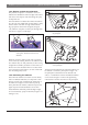
The signals picked up by the receiver are delayed by:
• the transmission from transmitter to radiator
through the cable (cable signal delay)
• the transmission from radiator to receiver through
the air (radiation signal delay)
• for systems with two or more transmitters: the
transmission through the slave transmitter(s)
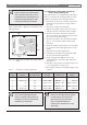
To compensate the signal delay differences, the delay of
each radiator can be increased. These signal delays can
be set with the delay switches at the back of the radiator.
The cable signal delays can be determined in the fol-
lowing two ways:
• by measuring the cable lengths
• by measuring the impulse response time with a
delay measurement tool
In both cases the cable signal delays can be calculated
manually and with the delay switch calculation tool
(available on the documentation CD-ROM).
It is not necessary to calculate the cable signal delay in
case:
• the radiators are directly connected to the transmit-
ter with equal cable length;
• radiators are loop-through connected, but with less
than 5 m distance between the first and last radiator
in a trunk, and with equal cable length between the
first radiator in each trunk and the transmitter.
In these cases set the delay switches on all radiators to
zero and determine whether to compensate for radia-
tion signal delay (see section 1.5.3).
The next sections describe how to calculate the delay
switch positions manually for systems with one trans-
mitter, or two or more transmitters. See the delay
switch calculation tool for the procedures how to calcu-
late the delay switch positions automatically.
1.5.1 System with one transmitter
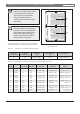
1.5.1.1 Determining delay switch positions by
measuring the cable lengths
Use the following procedure to determine the delay
switch position based on cable lengths:
1. Look up the cable signal delay per meter of the
used cable. The manufacturer specifies this factor.
2. Measure the lengths of the cables between the
transmitter and each radiator.
3. Multiply the lengths of the cables between the
transmitter and each radiator with the cable signal
delay per meter. These are the cable signal delays
for each radiator.
4. Determine the maximum signal delay.
5. Calculate for each radiator the signal delay differ-
ence with the maximum signal delay.
6. Divide the signal delay difference by 33. The
rounded off figure is the signal delay switch posi-
tion for that radiator.
7. Add delay switch positions for radiators under a
balcony, if applicable (see section 1.5.3).
8. Set the delay switches to the calculated switch posi-
tions.
INTEGRUS | Installation and User Instructions | System description and planning en | 9
Bosch Security Systems | 2005-04 | 3122 475 22015en
Tip: The delay switch calculation tool eases
the calculation of the delay switch positions.
Caution: Turn the delay switches carefully
to a new position until you feel that it
clicks into position, to prevent that a
switch is positioned between two num-
bers, which would result in a wrong delay
setting.