
user manual


2
Bosch Security Systems | 04-2003 | 3922 988 43318 en
Digital Congress Network | Installation and Operating Manual | Chapter 13 - Technical Data
en | 13-12
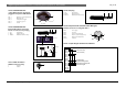
Connection details
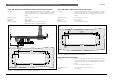
13.7.5 CONCENTUS units
5-pole XLR connector (female) for
pluggable microphones LBB 3549/xx
PIN 1 lightring control (active low)
PIN 2 lightring +5V
PIN 3 microphone signal
PIN 4 electrical ground
PIN 5 shield
13.7.6 CONCENTUS units
External Microphone connection
Stereo or mono 3.5 mm jack plug
1. Tip: Signal (live)
2. Ring: Signal (return)
3. Sleeve: Electrical earth/screen)
13.7.7 Cable connection
CINCH connector (male)
1 Signal +
2 Screen
13.7.8 Jack-plug
1. TIP: Signal (live)
2. RING: Signal (return)
3. Sleeve: Electrical earth/screen)
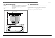
13.7.9 Interpreter desk (headset socket DIN-type)
Headset connector according IEC 268-11
PIN 1 Mic. supply
PIN 2 Mic. live
PIN 3 Left hand headphone
PIN 4 Return (both headphones)
PIN 5 Right hand headphone
Shield Ground
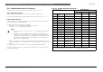
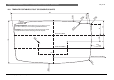
13.7.10 15-pole D-type connector PC Interface
1
2
34
5
Top view
3.5 mm
470 Ω
tip
ring
sleeve
1R
optional
213
1
2
321
5
4
31
2
PIN 1
PIN 2
PIN 3
PIN 4
PIN 5
PIN 6
PIN 7
PIN 8
PIN 9
PIN 10
PIN 11
PIN 12
PIN 13
PIN 14
PIN 15
+Ve (max. 40V)
+Ve (max 40V)
Up-link signal
Up-link screen/ground
Down-link screen/ground
Down-link signal