
user manual


2
Bosch Security Systems | 04-2003 | 3922 988 43318 en
Digital Congress Network | Installation and Operating Manual | Chapter 5 - Control using PC
en | 5-7
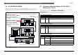
Connection PC to CCU
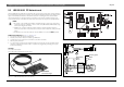
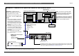
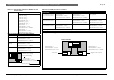
FIG 5-6 Example SINGLE-CCU system with control PC and Camera control
1
2
3
4
5
6
7
8
9
DCD
RD
TD
DTR
GND
DSR
RTS
CTS
RI
1
2
3
4
5
6
7
8
9
DCD
RD
TD
DTR
GND
DSR
RTS
CTS
RI
RS232RS232
CCU LBB 3500/15
PC
Male Female
9-pole D-type cable connections
Male
Male
Control PC
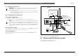
EXAMPLE 1: SINGLE-CCU system with control PC and Camera control
Port 1
Port 2
Rec.
Line
In
Out
In
Out
Symmetrical
Trunk
115V-T4A 230V -T2A
Control PC with
LBB 3500/15
‘wire-to-wire’
‘DIRECT’ DCN PC control
Power
Code Out
Alarm
Status
Battery Low
ALLEGIANT Video System
- CCU Port 1
- Protocol: FULL
Allegiant video switcher
Windows 95, 98, NT 4.0 or 2000
IMPORTANT: The LBB 3510/00 PC
Network card CANNOT be used in a PC
running Windows NT 4.0 or 2000.
Simultaneous use of the PC-Network card
and ‘DIRECT’ connection is NOT possible.
- Baudrate: 115.2k
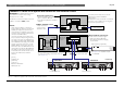
NOTES:
1. When using the ‘DIRECT’ method the
functions of the PC-Network card are
NOT available (i.e. headphones and
intercom). These functions are available
on the DCN Concentus units or with the
‘Multi-purpose connection unit’ LBB
3540/15.
2. The baud-rate setting of the PC COM-
port and the corresponding CCU Port
must be the same. If a different setting is
required this setting must be selected
accordingly:
CCU: DIP-switch S14 on TCB4.
PC: During DCN software installation
or in the dcn.ini file
- CCU Port 2
- Protocol: CAMERA
- Baudrate: 19.2k
NOTE: The number of required PC COM-
ports depend on the number of permanent
connections for peripheral devices (e.g. ID
chip-card encoder, and serial printer).
CAMERA control with Allegiant
The default functions of Port 1 and Port 2 can be interchanged or set for use with remote
control devices or for ‘Test/Diagnostic’ purposes instead of camera control by DIP-switch
(S14) on the TCB4 card (see Chapter 4.5 and Chapter 4.6).
video switcher
COM 2* COM 1
* The COM-port for CCU control is selected
during DCN software installation. COM 2 is
default when no ID chip card-encoder is used
(COM 3 is recommended otherwise).
see Note 2
(default)
Serial printer
See Chapter 6.. for installation details
DCN Trunk-lines
(see also Chapter 10.7)