
user manual


2
Bosch Security Systems | 04-2003 | 3922 988 43318 en
Digital Congress Network | Installation and Operating Manual | Chapter 6 - DCN Camera Control
en | 6-2
Allegiant Video Switcher
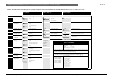
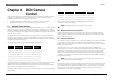
FIG 6-1 Range of BOSCH Allegiant Video Switchers
A maximum of 4 audience video displays can be connected to the Allegiant video switcher (not
applicable for video switcher LTC 8100 series) using outputs 2 to 5. The actual number set is defined
in the DCN Camera Control software LBB 3562 or LBB 3588. This option may save the need to use
a video distribution amplifier. Use of more than one video output for the audience may have a
negative influence on the system performance (response to events) for camera control.
Audience video displays shall be selected in accordance with the requirements of the conference
venue, e.g. large screen video projector(s), large screen monitors or TV-sets.
6.1.3 INSTALLATION
Requirements
1. To install Allegiant Video Switcher panel, video cameras and monitors.
2. To connect the DCN system to the Allegiant Video switcher panel.
3. To configure/set-up video cameras in relation to microphone activity for use in DCN stand-alone
and PC controlled systems.
CAUTION: When Installing and Operating the Allegiant Video Switcher/Control sys-
tem, cameras and monitors refer to the documentation delivered with the equipment.
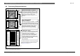
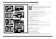
Connections to Allegiant Video Switcher Panel (see FIG 6-2 and FIG 6-3):
1. Using an RS232 cable terminated with 9-pole Sub-D connectors, connect the cable to the RS232
socket (‘Port 2 (default)) at the rear of the CCU to the 9-pole Sub-D socket marked
(‘CONSOLE’) at the rear of the Allegiant Video Switcher Panel.
FIG 6-3 shows the available RS232 cable connection for connecting the following configurations
1. Single CCU to video switcher
2. Installation PC to CCU and Video switcher
3. Connection OS/2 Master CCU to video switcher.
(This cable can be ordered under type number LTC 8506/00)
4. Installation PC to OS/2 Master CCU and Video switcher.
CAUTION: To meet EMC requirements all connections made to the ‘Port 1 output of the
CCU LBB 3500/xx or Port 1 and Port 2 of the CCU LBB 3500/05 or LBB 3500/35 must be
screened cables, where at least one side of the screening is connected to ground.
ALARM 1 - 5
BIPHASE OUT RELAY OUT
ALARM 9 - 16
ALARM 17 - 24 ALARM 25 - 32
KEYBOARD
CONSOLE
MONITOR
1
2
5
6
3
4
1
2
3
9
10
11
4
5
6
7
812
13
14
15
16
17
18
19
20
21
22
23
24
25
26
27
28
29
30
31
32
PRINTER
VIDEO 1 - 16
VIDEO 17 - 32
Power
Code Out
Alarm
Status
Battery Low
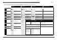
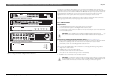
Front Panel Video Switcher LTC8300
Rear Panel Video Switcher LTC8300
Rear Panel Video Switcher LTC8200
Front Panel Video Switcher LTC8100/LTC 8200
Rear Panel Video Switcher LTC8100
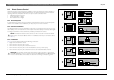
CONSOLE
KEYBOARD
CAMERA INPUTS
MONITOR OUTPUTS
LOOPING VIDEO
ALARM 1 - 8
RELAY OUT
BIPHASE OUT BIPHASE OUT
21
1 3456782
1 3456782
CONSOLE
KEYBOARD
MONITOR OUTPUTS
ALARM 1 - 8 ALARM 9 - 16 RELAY OUT
BIPHASE OUT BIPHASE OUT BIPHASE OUT
LOOPING VIDEO 1 - 16
21
9 10 11121314 1516
43 1 34567825
PowerBattery LowCode Out
ALLEGIANT Video System
StatusAlarm
ALLEGIANT Video System