
user manual

2
Bosch Security Systems | 04-2003 | 3922 988 43318 en
Digital Congress Network | Installation and Operating Manual | Chapter 6 - DCN Camera Control
en | 6-7
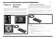
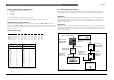
Direct Camera Control
6.2.4 Set-up Camera Configuraion
Reference: To configure and set-up camera positions according to delegate/chairman
microphone activity, DCC is available for Stand-alone DCN systems using DCN
software package LBB 3562/00 and LBB 3588/00 for PC controlled systems.
Refer to the relevant software manuals when programming the
configuration for the DCC system.
To install and download the required software modules proceed as described in the following
sections.
For camera installation with stand-alone Camera Control software LBB 3562/00 a temporary PC
connection is required.
The minimum PC requirements are as follows:
• Pentium II processor
• 48 MB RAM
• Video card supporting at least VGA and SVGA resolutions
• Hard disk with a data access time of 14 ms
• 100 MB free disk space
• Ethernet network card for multi-PC systems
• Serial port (RS232)
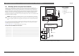
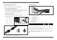
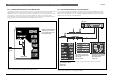
6.2.4.1 Stand-alone DCN system
The following procedure describes the connection of a PC with one COM-port. If you use a PC with
two COM-ports you can connect the CCU to the second COM-port. It is not necessary to
disconnect the AutoDome camera (item 6).
1. Connect the AutoDome to the PC-COM-port (RS232).
2. Connect a monitor to the video output of the AutoDome via a 75 Ohm coax cable.
3. Install the virtual keyboard software LTC 5138 (see enclosed Instructions for Use).
The required AutoDome communication settings are:
• 9600 baud
• 8 data bits
• No parity
• 1 stop bit
• No handshaking
4. Set the camera prepositions for the microphone positions in the room. The highest preposition is
used for an overview picture.
5. Close the virtual keyboard application.
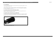
6. Connect the CCU (LBB 3500/x5) to the PC COM-port (disconnect the AutoDome)
The required CCU communication settings are (see paragraph 4.6):
• Camera control protocol
• 9600 baud
7. Install the DCN stand-alone camera control software LBB 3562/00 on the PC and assign the
defined AutoDome prepositions to the DCN units (See the LBB 3562 software manual).
8. Disconnect the CCU from the PC.
9. Connect the AutoDome to the CCU.
NOTE: Re-adjustments of the stored AutoDome prepositions can only be done with the
AutoDome connected to the temporary or DCN control PC with virtual keyboard software.
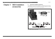
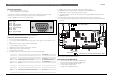
6.2.4.2 DCN PC controlled system with single CCU
The following procedure describes the connection to a PC with one COM-port. If you use a PC with
two COM-ports you can connect the AutoDome camera to the second COM-port. It is not
necessary to disconnect (item 1) and reconnect (item 7) the CCU. The procedure assumes that you
have an installed DCN system with PC control with an LBB 3500/15(D) or LBB 3500/35(D) CCU.
1. Disconnect the control PC from the CCU.
2. Connect the AutoDome to the PC COM-port (RS232)
3. Connect a monitor to the video output of the AutoDome via a 75 Ohm coax cable.
4. Install the Virtual keyboard software LTC 5138/00 (see enclosed Instructions for Use).
The required AutoDome communication settings are:
• 9600 baud
• 8 data bits
• No parity
• 1 stop bit
• No handshaking
5. Set the camera prepositions for the microphone positions in the room. The highest preposition is
used for an overview picture.
6. Close the virtual keyboard application.
7. Connect the CCU to the PC COM-port (disconnect the AutoDome)
The required CCU communication settings are:
• Fulll protocol
• 115200 baud
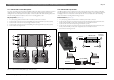
8. Connect the AutoDome camera to Port 2 of the CCU.
The required CCU communication settings are:
• Camera control protocol
• 115200 baud
9. Install the DCN camera control software LBB 3588/00 on the PC and assign the defined
AutoDome prepositions to the DCN units (See the LBB 3588 software manual).
10. Check the DCN system with DCC functionality.
NOTE: Re-adjustments of the stored AutoDome prepositions can only be done with the
AutoDome connected to the temporary PC with Virtual Keyboard software.
DCN
Software
Manuals
BOSCH