DCN Voting Units en Installation and User Instructions DCN Voting Units LBB 4141/00 and LBB 4141/50
DCN Voting Units Installation and User Instructions en | 2 Important Safeguards About this Manual Prior to installing or operating this product always read the Safety Instructions, which are available as a separate document. Purpose The purpose of the Installation and User Instructions is to provide information required to install and operate a DCN system with voting units LBB 4141/00 and LBB 4141/50.
DCN Voting Units Installation and User Instructions Table of contents 1 2 2.1 2.2 2.3 2.4 2.4.1 2.4.2 2.4.3 2.5 2.6 2.6.1 2.6.2 2.6.3 2.6.4 2.6.5 2.7 2.8 2.8.1 2.8.2 2.8.3 2.8.4 2.8.5 2.8.6 2.9 2.9.1 2.9.2 2.9.3 2.9.4 2.10 Introduction................................................................... 4 Voting Units and Accessories ............................. 5 Introduction............................................................... 5 Controls, Connectors and Indicators .................
DCN Voting Units Installation and User Instructions 1 Introduction The LBB 4141/00 and LBB 4141/50 voting units are part of the DCN range. This manual only contains the information specific for installing and using the LBB 4141/00 and LBB 4141/50 voting units.
DCN Voting Units Installation and User Instructions 2 en | 5 Voting Units and Accessories 5 4 4 2.1 Introduction The voting unit range consist of: • LBB 4141/00 Voting Unit • LBB 4141/50 Chinese Voting Unit • LBB 4125/00 Set of 50 End Caps • LBB 4127/00 Set of 50 Coupling Pieces Figure 2.4 LBB 4127/00 (Set of 50) Coupling Pieces This chapter describes how to install and use these units. 6 7 2.2 Controls, Connectors and Indicators 8 9 1 Figure 2.
DCN Voting Units Installation and User Instructions en | 6 2.4 Mounting The LBB 4141/00 and LBB 4141/50 voting units can be snap-mounted and block mounted. 2.4.1 Snap Mounting Figure 2.6 Changed Voting Button Order LBB 4141/00 To change the voting button order: 1 Unscrew the front plate of the voting unit. Keep the two screws. 2 Remove the three buttons in the middle of the unit by squeezing the snap fingers of the buttons with a pair of tweezers. 3 Insert the buttons in the correct position.
DCN Voting Units Installation and User Instructions mounting. In stage 3: fasten the screws of the coupling pieces, in order to fixate the coupling pieces. en | 7 2.4.3 De-mounting Follow the mounting procedure in reverse. Use a spatula to remove the end caps and a screwdriver to unlock the click-to-fit mechanism of the voting unit. > i Note Take care not to damage the furniture while removing the end caps and voting unit. Replace the end caps in case those are damaged. 2.
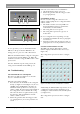
DCN Voting Units Installation and User Instructions en | 8 2.6.1 De-initialization of a System Systems, which are powered-up for the first time, are de-initialized. All LEDs of the de-initialized units illuminate. In case some of the units are not in this state, de-initialize these units or de-initialize the system. See chapter 11 of the DCN Installation and Operating Manual for how to de-initialize a system. 2.6.
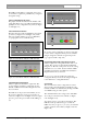
DCN Voting Units Installation and User Instructions en | 9 The LBB 4141/50 Chinese voting unit can be used for attendance registration, parliamentary voting and for/against voting. 2.8.2 Locating Buttons by Touch The pimple beneath the button in the middle of the voting unit allows users, especially visual impaired to quickly locate the voting buttons by touch (see Figure 2.1 and Figure 2.2) Figure 2.18 Presence Registration LBB 4141/00 2.8.
DCN Voting Units Installation and User Instructions en | 10 If the unit active indicator does not illuminate: 1. Check whether the unit is connected. 2. Follow the general trouble shooting procedure (see paragraph 2.9.4). Figure 2.20 Parliamentary Voting LBB 4141/00 2.9.2 Address Conflict In some cases the voting unit cannot detect an address conflict.
DCN Voting Units Installation and User Instructions Figure 2.23 Pop up warning via LBB 3590 software In case a disconnect is detected: check the fault indication on the related unit and follow the instructions of paragraph 2.9.1. If, however, the unit active indicator of the associated unit illuminates: 1. Check whether the fault is caused by an address conflict. See paragraph 2.9.2. 2. Follow the general trouble shooting procedure (see paragraph 2.9.4), in case the problem is not solved 2.9.
For more information please visit www.boschsecuritysystems.com © 2004 Bosch Security Systems B.V.