D8125MUX Operation and Installation Guide EN Multiplex Bus Interface
EN | 2 Contents Contents...........................................................................2 1.0 Introduction ......................................................3 1.1 Description..........................................................3 1.2 Programming......................................................3 1.3 Listings ................................................................3 2.0 Operation...........................................................4 3.0 Installation......................
D8125MUX | Operation and Installation Guide | 1.0 Introduction . 1.0 Introduction 1.1 Description Use the D8125MUX Multiplex Bus Interface Module to connect multiplex points to the zonex bus on the following Bosch Security Systems control panels: D9412GV2, D7412GV2, D7212GV2, D9412G, D7412G, D7212G, D9412, D7412, D7212, D9112, and D9124 with version 5.22 or greater firmware. Install the D8125MUX on Zonex 1 and Zonex 2 (D9412GV2, D9412G, D9412, and D9112 only).
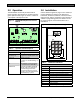
D8125MUX | Operation and Installation Guide | 2.0 Operation 2.0 Operation 3.0 Installation The D8125MUX continuously monitors itself for proper operation and indicates its condition using the green Operation LED (Figure 1). Refer to Table 1 for a description of the Operation LED. Use the D5060 Programmer (Figure 2 and Table 2) to program multiplex bus points for the D9412GV2, D7412GV2, D7212GV2, D9412G, D7412G, D7212G, D9412, D7412, D7212, and D9112 Control Panels.
D8125MUX | Operation and Installation Guide | 3.0 Installation . 3.1 Connecting the D5060 Programmer Figure 4: 1. When using external power, attach the flying leads of the included power cable to the output terminals of a 16.5 VAC transformer. Insert the plug end into the jack labeled EXT. POWER on the programmer. Refer to Figure 3, Figure 4, and Figure 5. 2. Use the serial cable provided to connect the D8125MUX to the jack labeled SERIAL PORT on the programmer. 3.
D8125MUX | Operation and Installation Guide | 3.0 3.2 Programming 3.2.1 Powering the D5060 Turn on the D5060 by pressing and holding the [1] key until the unit beeps. To turn the unit off, press and hold the [#] and [*] keys simultaneously until the unit beeps. After 5 minutes of inactivity, the programmer powers down automatically to conserve power. 3.2.2 Programming Points 1. The D5060 shows the prompt Adr after it is powered. This indicates that it is ready to begin programming. 2.
D8125MUX | Operation and Installation Guide | 3.0 . 3.2.4 Interrogation Mode You can also use the programmer to read information from the D8125MUX and multiplex points. Refer to Section 3.1 Connecting the D5060 Programmer on page 5 to install the D5060. Reading Information from the D8125MUX 1. To enter Interrogation Mode, press and hold [7] and [9] simultaneously until the unit beeps. 2. The LED marked INTERROGATION MODE lights. A.dr appears prompting you to enter a starting address. 3.
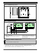
D8125MUX | Operation and Installation Guide | 3.0 Figure 6: Installation D8125MUX Mounting Locations 1 1 1 - Module mounting location Figure 7: D8125MUX Wiring Diagram 1 Operation Monitor Pulses When Normal Flickers When Ringing GRN Reset Pin Disable All Except Battery Charging And Programming PERIPHERAL DEVICE WIRING POWER + 32 YELLOW DATA BUS A 31 GREEN DATA BUS B 30 BLACK COMMON 29 ZONEX OUT 1 28 ZONEX IN 1 27 ZONEX OUT 2 26 RED RESET 12V N.F.P.A. Style 3.
D8125MUX | Operation and Installation Guide | 3.0 Installation . Figure 8: Wiring the D8125MUX to Detection Systems Multiplex Points Table 4: D8125MUX Line Length MUX BUS A Maximum Wire Impedance: 33 Ω AWG (mm) Length in Ft (m) D8125MUX POWER A MUX BUS A 22 (0.8 mm) 18 (1.2 mm) MUX BUS B POWER B MUX BUS B + - + - + - + - Maximum Wire Impedance: 33 Ω AWG (mm) Length in Ft (m) 2 1 22 (0.8 mm) 2000 (610)* 18 (1.2 mm) 5000 (1524)* * 3 5 1234- 3.
D8125MUX | Operation and Installation Guide | 3.0 3.7 Installing a Multiplex Device As shown in Table 6, several types of multiplex devices are available. Each multiplex accessory device is packaged with instructions connecting to the multiplex bus output.
D8125MUX | Operation and Installation Guide | 3.0 Installation . Table 7: Point Conversion Table If Zonex 2 Pt. # is Program as If Zonex 2 Pt. # is Program as If Zonex 2 Pt. # is Program as If Zonex 2 Pt. # is Program as If Zonex 2 Pt.
D8125MUX | Operation and Installation Guide | 3.
D8125MUX | Operation and Installation Guide | 3.0 Installation .
D8125MUX | Operation and Installation Guide | 3.
D8125MUX | Operation and Installation Guide | 3.0 Installation .
D8125MUX | Operation and Installation Guide | 3.
D8125MUX | Operation and Installation Guide | 3.0 Installation .
D8125MUX | Operation and Installation Guide | 3.0 Table 10: Switch Number (• = ON) 1 189/190 191/192 193/194 195/196 197/198 199/200 201/202 203/204 205/206 207/208 209/210 211/212 213/214 215/216 217/218 219/220 221/222 223/224 225/226 227/228 229/230 231/232 233/234 235/236 237/238 239/240 241/242 243/244 245/246 247/248 18 3.
D8125MUX | Operation and Installation Guide | 3.0 Installation . 3.10 MX250 Photoelectric Smoke Detectors and MXB2W Base or D7050 Photoelectric Smoke Detector and D7050-B6 Base The MX250 and MX250TH Photoelectric Smoke Detectors with MXB2W Base or D7050 and D7050TH Photoelectric Smoke Detectors and D7050-B6 Base reserve a single point on the multiplex bus.
D8125MUX | Operation and Installation Guide | 3.0 3.12 DS7432 Eight Input Remote Module This device type reserves eight points on the multiplex bus. Each D8125MUX supports fifteen DS7432s on the D9412GV2, D9412G, D9412, and D9112 Control Panels, up to eight on the D7412GV2, D7412G, D7412, and D7212 Control Panels, and up to four on the D7212GV2 and D7212G Control Panels.
D8125MUX | Operation and Installation Guide | 4.0 . Control the relay output on each DS7465 using any of the following control panel options: • Relay follows Point for Points 9 through 64 (Points 9 through 34 for D7212GV2/D7212G) (refer to the Relay Response Type section in the control panel’s program entry guide). When the DS7465i is programmed to follow a point, the relay can have a delayed response of 2 to 5 sec.
D8125MUX | Operation and Installation Guide | 5.0 Troubleshooting 5.0 Troubleshooting Table 17: Troubleshooting Symptom Diagnosis Remedy Multiplex point appears as missing at the keypads. Multiplex point is not connected to MUX bus. Check wiring. Points intermittently appear as missing. Multiplex point not programmed. MUX bus wires not connected to D8125MUX. Noise problem on MUX bus loop. Verify that a multiplex point programmed for the missing multiplex point is connected to the MUX bus wiring.
D8125MUX | Operation and Installation Guide | 5.0 Troubleshooting Table 17: EN | 23 Troubleshooting (continued) Symptom Diagnosis Remedy All off-board points report as MISSING. Short on Aux power, Terminal 3 or Zonex power, Terminal 24. If only one D8125MUX is connected to the control panel, the D8125MUX might be incorrectly connected to the control panel, or MUX bus wiring might be disconnected from the D8125MUX. Multiplex power terminals or MUX bus terminals on DS7432 might be incorrectly wired.
Bosch Security Systems, Inc. 130 Perinton Parkway Fairport, NY 14450-9199 (800) 289-0096 © 2008 Bosch Security Systems, Inc.