
user manual


D8125MUX | Operation and Installation Guide | 2.0 Operation
4 Bosch Security Systems, Inc. | 10/09 | F01U034973-02
2.0 Operation
The D8125MUX continuously monitors itself for
proper operation and indicates its condition using the
green Operation LED (
Figure 1). Refer to Table 1 for
a description of the Operation LED.
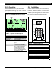
Figure 1: D8125MUX Multiplex Bus Interface
Module
RESET
12V IN OUT GND
ZONEX BUS
FIRE MANUAL
WALK TEST
PROG
PORT
+- +- + - +-
POWER A
MUX BUS A
POWER B
MUX BUS B
1
1 - Operation LED
Table 1: Operation LED Descriptions
LED Status Meaning
Flashing 1/2
second on, 1/2
second off
The D8125MUX scans its
programmed multiplex points and
operates normally.
Off A module fault is indicated. Refer
to Section
5.0 Troubleshooting on
page
22.
On The Multiplex Point Programmer
is connected to the D8125MUX.
Double flash Reset the D8125MUX EEPROM
with the reset pin by plugging in
the D5060 Programmer and
placing the shorting bar over the
reset pin. The LED rapidly flashes
twice followed by a pause.
3.0 Installation
Use the D5060 Programmer (Figure 2 and Table 2) to
program multiplex bus points for the D9412GV2,
D7412GV2, D7212GV2, D9412G, D7412G, D7212G,
D9412, D7412, D7212, and D9112 Control Panels. In
addition to programming points, the D5060 can also
be used to program and read information from a
D8125MUX.
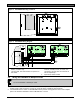
Figure 2: D5060 Multiplex Point Programmer
EXT.
POWER
SERIAL PORT MUX
POINTS
INTERROGATION MODE
ON
(HOLD)
YES NO
DOWN
UP
CLEAR
ENTER
OFF
(HOLD)
INTERROGATE
(HOLD)
MULTIPLEX POINT PROGRAMMER
1
3
4 56
7 8
9
*
0
#
2
Table 2: D5060 LED Definitions
Display Definition
Adr Enter address.
A.dr Enter address for Interrogation Mode.
bAd Battery voltage is below 15 V.
Err Point was not programmed correctly.
Lob Battery voltage is below 16 V.
noP No response from point.
PnL Communications with the D8125 failed.
rSP Point responds to address.
tYP Enter point type.
t.YP Enter point type for Interrogation Mode