
user manual


D8125MUX | Operation and Installation Guide | 3.0 Installation
.
Bosch Security Systems, Inc. | 9/08 | F01U034973-02 5
3.1 Connecting the D5060 Programmer
1. When using external power, attach the flying
leads of the included power cable to the output
terminals of a 16.5 VAC transformer. Insert the
plug end into the jack labeled EXT. POWER on
the programmer. Refer to
Figure 3, Figure 4, and
Figure 5.
2. Use the serial cable provided to connect the
D8125MUX to the jack labeled SERIAL PORT on
the programmer.
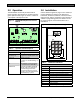
3. For multiplex devices without DIP switches, use
the multiplex programmer cable provided to
connect the point to be programmed to the port
labeled MUX POINTS as shown in
Figure 3. Use
the appropriate connector, either the alligator
clips or the probes, to connect the programmer to
a point.
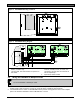
For multiplex points with programmable DIP
switches, program the point using the DIP
switches. Connect the programmer to the
D8125MUX as shown in
Figure 4.
Figure 3: Installing Multiplex Points without
DIP Switches Wiring Diagram
EXT.
POWE R
SERIAL PORT MUX
POINTS
INTERROGATION MODE
RES ET
12V IN OUT GND
ZONEX BUS
FIR E MANU AL
WALK T EST
PROG
PORT
+- +-+ - + -
POWER A MUX BUS A
POWER B
MUX B US B
1
2
3
4
1 - External power
2 - D8125MUX
3 - Multiplex point without DIP switches
(non-i models)
4 - D5060 Multiplex Point Programmer
Figure 4: Installing Multiplex Points with DIP
Switches Wiring Diagram
EXT.
POWER
SERIAL PORT MUX
POINTS
INTERROGATION MODE
RES ET
12V IN OUT GND
ZONEX BUS
FIRE MANUAL
WALK TEST
PROG
PORT
+- +- + - +-
POWE R A MUX BU S A
POWER B
MUX BUS B
1
2
3
1 - External power
2 - D8125MUX
3 - D5060 Multiplex Point Programmer
Figure 5: Programmer Cables (included)
1
2
3
1 - C310 Serial Cable
2 - C319 External Power Supply Cable
3 - C320 Multiplex Programmer Cable