
user manual


D8125MUX | Operation and Installation Guide | 3.0 Installation
.
Bosch Security Systems, Inc. | 9/08 | F01U034973-02 7
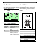
1. Align the D8125MUX with any of the three
mounting locations shown in
3.2.4 Interrogation Mode
Figure 6 on page 8.
Then fasten the module with the three mounting
screws provided.
You can also use the programmer to read information
from the D8125MUX and multiplex points. Refer to
Section
3.1 Connecting the D5060 Programmer on
page
2. Remove AC and DC power from the control
panel.
5 to install the D5060.
Reading Information from the D8125MUX
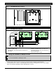
3. Connect 12 V from the D8125MUX to Zonex
Power +, Terminal 24, on the D9412GV2,
D7412GV2, D7212GV2, D9412G, D9412, and
D9112 (Terminal 3 on the 7412G, D7212G,
D7412, and D7212) as shown in
1. To enter Interrogation Mode, press and hold [7]
and [9] simultaneously until the unit beeps.
2. The LED marked INTERROGATION MODE
lights.
Figure 7 on
page
8.
A.dr appears prompting you to enter a starting
address.
4. Connect IN on the D8125MUX to Zonex Out 1,
Terminal 28 (or Zonex Out 2 Terminal 26) on the
control panel.
3. Enter an address followed by [#].
The Interrogation LED flashes.
5. Connect OUT on the D8125MUX to Zonex In 1,
Terminal 27 (or Zonex In 2 Terminal 25) on the
control panel.
4. Press [#] to read point information from the
D8125MUX at that address.
5. Press [4] to read the previous address
information from the D8125MUX.
6. Connect GND on the D8125MUX to Zonex
Common, Terminal 23, on the D9412GV2,
D7412GV2, D7212GV2, D9412G, D9412, and
D9112 (Terminal 9 on the D7412G, D7212G,
D7412, and D7212).
6. Press [6] to read the next address information
from the D8125MUX.
If communication between the unit and
7. Connect Power A + and Power A - on the
D8125MUX to multiplex devices that require
auxiliary power. Up to 200 mA are available at
these terminals.
the D8125MUX fails, the unit sounds a
three-beep error tone and shows PnL.
7. Exit Interrogation Mode by pressing and holding
[*] until the unit beeps.
8. Connect MUX BUS A + and A - on the
D8125MUX to the positive and negative bus wires
of the multiplex points.
Reading Information from MUX Points
9. When using Loop B, connect Power B (if
applicable) and MUX BUS B on the D8125MUX
to the power and bus wires of the multiplex
points. Power B+ and B- also have up to a 200
mA capacity. Observe correct polarity.
Disconnect all multiplex points from the
D8125MUX and the multiplex bus before
reading multiplex point information.
1. To enter Interrogation Mode, press and hold [7]
and [9] simultaneously until the unit beeps. The
LED marked INTERROGATION MODE lights.
Ensure the D8125MUX is not powered
before connecting or disconnecting
multiplex devices. Connecting or
2. The display reads A.dr prompting you to enter a
starting address. Enter an address and press [#].
disconnecting a multiplex device while the
D8125MUX is powered causes the
3. Press [1].
multiplex device address setting to
4. When t.YP appears at the keypad, enter the point
type of the multiplex point as shown in
reprogram or scramble.
Table 3 on
page
6 and press [#].
5. If a point responds to the address, the
programmer beeps once and rSP appears. If the
point does not respond, the unit beeps three
times and the display reads noP.
6. Exit Interrogation Mode by pressing and holding
[*] until the unit beeps.
3.3 Installing and Wiring the
D8125MUX to the Control Panel
The D8125MUX is installed in the control panel
enclosure and is connected to either Zonex 1 or
Zonex 2 on the control panel.