
user manual


D8125MUX | Operation and Installation Guide | 3.0 Installation
8 Bosch Security Systems, Inc. | 10/09 | F01U034973-02
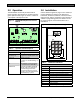
Figure 6: D8125MUX Mounting Locations
1
1
1 - Module mounting location
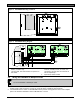
Figure 7: D8125MUX Wiring Diagram
PERIPHERAL DEVICE WIRING
ZONEX OUT 1
ZONEX IN 1
ZONEX OUT 2
ZONEX IN 2
ZONEX POWER +
ZONEX COMMON
Operation Monitor
Pulses When Normal
Flickers When Ringing
PROG
CONN
RED
YELLOW
GREEN
BLACK
32
POWER +
DATA BUS A
COMMON
Reset Pin
Disable All Except Battery
Charging And Programming
GRN
N.F.P.A.
Style 3 .5
Signaling
Line
Circuits
DATA BUS B
29
31
30
24
23
28
27
26
25
RESET
12V IN OUT GND
ZONEX BUS
FIRE MANUAL
WALK TEST
PROG
PORT
+- +- + - +-
POWER A
MUX BUS A
POWER B
MUX BUS B
RESET
12V IN OUT GND
ZONEX BUS
FIRE MANUAL
WALK TEST
PROG
PORT
+- +- + - + -
POWER A
MUX BUS A
POWER B
MUX BUS B
1
2
3
4
1 - D9412GV2, D7412GV2, D7212GV2, D9412G,
D9412, or D9112 only.
3- When connecting the D8125MUX to a
D7412G, D7212G, D7412, or D7212, use
Terminals 3 and 9 in place of Terminals 24
and 23 respectively.
2 - The Fire Walk Test terminal does not operate on
this model.
4 - Supervised, Power Limited.
3.4 Wiring the D8125MUX to Multiplex Points
Do not use shielded or twisted pair cable.
1. Connect Power A+ and Power A- on the D8125MUX to multiplex devices that require uninterrupted
auxiliary power. Refer to Figure 8 on page 10. Up to 200 mA is available at these terminals.
2. Connect MUX BUS A+ and A- on the D8125MUX to the positive and negative bus wires of the multiplex
points. The maximum allowable current on MUX BUS A is 75 mA.