
user manual


D8125MUX | Operation and Installation Guide | 3.0 Installation
.
Bosch Security Systems, Inc. | 9/08 | F01U034973-02 9
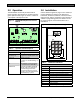
Figure 8: Wiring the D8125MUX to Detection
Systems Multiplex Points
Table 4: D8125MUX Line Length
+
-
+
-
+
-
+-
POWER A
MUX BUS A
POWER B
MUX BUS B
D8125MUX
1
2
3
4
5 6
7
8
MUX BUS A
Maximum Wire Impedance: 33 Ω
AWG (mm) Length in Ft (m)
22 (0.8 mm) 2000 (610)*
18 (1.2 mm) 5000 (1524)*
MUX BUS B
Maximum Wire Impedance: 33 Ω
AWG (mm) Length in Ft (m)
22 (0.8 mm) 2000 (610)*
18 (1.2 mm) 5000 (1524)*
* Current requirements for multiplex points vary. The maximum
allowable distance you can locate remote points might be
reduced. Do not exceed 75 mA maximum on each MUX bus
output.
Table 5: Control Panel to D8125MUX
Distance
1 - To Loop B BUS – 5 - To Loop A BUS –
2 - To Loop B BUS +
3 - To Loop B Power –
4 - To Loop B Power +
6 - To Loop A BUS +
7 - To Loop A Power –
8 - To Loop A Power +
Maximum Impedance: 4.05 Ω at +68°F (+20°C)
nominal
Maximum Distance Size
250 ft 22 AWG
3.5 Using Power B and MUX BUS B
(Optional)
600 ft 18 AWG
76 m 0.65 mm
It might be necessary to use the Power B (+, -) and
MUX BUS B (+, -) terminals for isolation purposes.
For example, an Authority Having Jurisdiction (AHJ)
might require that fire points and burglar points be on
independent buses.
193 m 1.02 mm
Fire applications require 18 AWG.
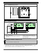
Figure 9: Wiring Multiplex Devices to MUX
Bus
1. Connect Power B+ and Power B- on the
D8125MUX to multiplex devices that require
uninterrupted auxiliary power. Up to 200 mA is
available at these terminals.
D8125MUX
D8125MUX
1
1
2. Connect MUX BUS B + and B - on the
D8125MUX to the positive and negative bus wires
of the multiplex points. The maximum allowable
current on MUX BUS B is 75 mA.
3.6 Wiring Multiplex Devices to the
Multiplex Bus
Use one two-wire data expansion loop using MUX
BUS A, or distribute the devices on both MUX BUS A
and B.
Table 4 shows the maximum distance per
MUX bus output - each D8125MUX has two multiplex
bus outputs.
Table 5 shows the maximum distance
between the control panel and the D8125MUX.
Determine the required wire gauge for each multiplex
bus expansion loop (
Table 4). Programming the
individual multiplex points with the D5060 assigns
them to point numbers. Daisy chain and T-tapping
configurations are acceptable. Refer to
1 - Multiplex device
Figure 9.