
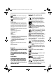
Instructions


English | 27
Bosch Power Tools F 016 L81 767 | (29.11.17)
Explanation of Installation Guide
(see pages 3–7)
Installation
For a video guide on how to install the Indego please visit
www.bosch-indego.com or use the following QR-Code. Alter-
natively follow the installation guide delivered with the prod-
uct.
Remove thatch, stones, loose pieces of wood, wire, live mains
cables and other foreign objects from the cutting area.
Make sure that the cutting area is even and has no ditches,
grooves and steep slopes above 15° that are clear obstruc-
tions for the machine.
Make sure the cutting area is free of small animals such as
hedgehogs or tortoises.
Note: The docking station must be positioned on the wire at
an outer edge of the cutting area. It cannot be positioned by
the side of a shed or workshop that appears as an island with-
in the cutting area.
Note: The maximum distance between perimeter wire and In-
dego at any point within the mowing area must not exceed 16
m.
Objects on the lawn below 5 cm height e.g. ponds, flower
beds etc. must be delimited in a clockwise direction around
the object.
Note: If extra perimeter wire is required this can be added us-
ing a wire connector. (see figures 3–4)
The wire can be extended up to a total maximum allowed
length of 250 m.
The perimeter wire can be buried up to 5 cm under the ground
(or non-metallic slabs) if verticutting or raking is intended,
avoid the perimeter wire area.
When laying out the wire avoid angles of less than 45 °. This
can affect performance.
Screen
The display switches into sleep mode, if no input is made for
10 minutes.
Mowing
Do not let children ride the machine.
Press stop button on top of the mower before lifting.
Always lift the machine at its handle. (See figure 5)
After a successful installation you can either immediately be-
gin to mow by confirming “Mow now” with the confirm button
or wait for the next scheduled cutting period, as programmed
by the Bosch AUTO Calendar Function (previous acceptance
required).
A mowing schedule can also be set up according to your
needs. Approximate runtimes to complete a full garden cov-
erage are quoted below. Please note that the runtimes will
va ry dep en din g on the law n c omplexity and number of objects
within the lawn area.
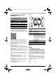
Action Figure Page
Delivery scope/unpacking product
1 4
Lay out perimeter wire
2 4
Extend perimeter wire
3 5
Lay perimeter wire around new inner
object
4 5
Lift up and carry the machine
5 6
Set height of cut
6 6
Cleaning
A 7
Maintenance
B 7
Symbol Meaning
Back button
Confirm button
Wake up button
Red LED on: mower error
Green LED on: mower is on
Green LED off: Product is inactive and it
will require your four digit PIN code to ac-
tivate the mower. Or the product is isolat-
ed, and it will require the isolator switch to
be turned on and your four digit PIN code
to activate the mower.
Left, right button
Down, up button
Display with dialog screen
100 m
2
4 h
350 m
2
12 h
400 m
2
14 h
OBJ_BUCH-3008-003.book Page 27 Wednesday, November 29, 2017 12:20 PM