IMPORTANT: Read Before Using IMPORTANT : Lire avant usage IMPORTANTE: Leer antes de usar Operating/Safety Instructions Consignes de fonctionnement/sécurité Instrucciones de funcionamiento y seguridad GPL5 L5 GP Call Toll Free for Consumer Information & Service Locations Pour obtenir des informations et les adresses de nos centres de service après-vente, appelez ce numéro gratuit Llame gratis para obtener información para el consumidor y ubicaciones de servicio 1-877-BOSCH99 (1-877-267-2499) www.
-2-
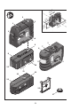
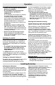
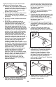
/4” 1 1mm) (32 2 ” 3/4mm) (20 3 1 L5 GP 1 /4” 1 1 m) ” 3/4 ) (45 (32 mm /4” 2 3mm) (32 m 1 L5 GP 1 4 1 9 7 6 8 L5 GP 1 5 10 12 11 12 14 13 15 17 -3-
General Safety Rules Read all instructions. Failure to follow all instructions listed below may ! WARNING result in hazardous radiation exposure, electric shock, fire and/or serious injury. The term “tool” in all of the warnings listed below refers to your mains-operated (corded) tool or battery-operated (cordless) tool. The following labels are on your laser tool for your convenience and ! WARNING safety. They indicate where the laser light is emitted by the tool.
Use and care Use the correct tool for your application. The correct tool will do the job better and safer. Do not use the tool if the switch does not turn it on and off. Any tool that cannot be controlled with the switch is dangerous and must be repaired. Store idle tool out of the reach of children and do not allow persons unfamiliar with the tool or these instructions to operate the tool. Tools are dangerous in the hands of untrained users. Maintain tools.
Intended Use This tool projects plumb and horizontal points and is intended for accurate transfer and alignment of plumb, level, graded and 90-degree points Preparation counterclockwise direction to the position. When the laser beams flash slowly during operation,the batteries are low. When the flashing begins, the tool can be operated for approx. 8 h. Always replace all batteries at the same time. Only use batteries from one brand and with the identical capacity.
Operation minutes to 8 hours. For this, switch the tool on, then immediately off, and then on again within 4 s. To confirm the change, all laser beams will flash quickly for 2 s after switching on the second time. • Do not leave the switched on tool unattended and switch the tool off after use. Other persons could be blinded by the laser beam. When switching on the tool the next time, the automatic switch-off is set to 20 minutes again.
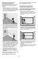
Checking the Horizontal Leveling Accuracy of the Lateral Axis Thus, the difference d between points I and II may not exceed 9/16 in (max.). A free measuring distance of 78 ft on a firm surface in front of a wall is required for the check. Checking the Horizontal Leveling Accuracy of the Longitudinal Axis – Mount the measuring tool onto the multipurpose attachment or a tripod, or place it on a firm and level surface at a distance of 78 ft to the wall. Switch the tool on.
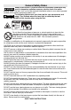
A B 13 ft – Position the tool in such a manner that the upper plumb beam points against the line on the ceiling. Allow the tool to level in. Mark the center of the upper laser point on the line on the ceiling (point I). Also, mark the center of the laser point on the floor (point II). – Align the height of the tool (using the tripod or by underlaying, if required) in such a manner that the center point of the laser beam is projected exactly against the previously marked point II on wall B.
significant impact, the user should check calibration by following these steps: 1. Select a site to be used as a calibration range that will allow the tool to be placed between two smooth vertical surfaces directly opposite each other at a 100' distance. (50' minimum) 2. Remove the two calibration plugs on the rear and side of tool with a flathead screwdriver. Set the plugs where they will not be lost. 3. Set tool on a level surface at one end of the range. 4.
12. Rotate the tool around 90 degrees and position the front laser beam on the vertical surface. Compare the height of this beam with the height of the calibrated side beams. If the height of this beam matches the height of the side beams, calibration is complete and you may exit calibration mode. To exit Calibration mode, push the power switch into the CAL (override) position and hold for 5 seconds. The laser beams will flash rapidly for the 5 seconds until it exits calibration mode.
3. Measure distance A and make a note of the distance. 4. Measure distance B at distance X away from A and note these distances. 5. Slope = (B – A)/X Note: To calculate Pitch, set X equal to 12”. Grade Transferring points with the plumb beam 1. Mark the point to be transferred (labeled A in this illustration). 2. Use the Mounting accessory or a Tripod to position the plumb down beam over point A. 3. The plumb up beam will transfer this point along a perfectly vertical axis to point B. 4. Mark point B.
Square 10. If distance Y equals distance Z, then the two surfaces are square. If distance Y does not equal distance Z, then adjust the position of the surface which these distances relate to until distance Y does equal distance Z. Note: The plumb beams can also be used in operations such as squaring window frames. A B Y Z Use with Attachments locking screw of the tripod tight.
Maintenance and Service In all correspondence and spare parts orders, please always include the 10-digit article number given on the type plate of the tool. Store and transport the tool only in the supplied protective case. Keep the tool clean at all times. Do not immerse the tool into water or other fluids. In case of repairs, send in the tool packed in its protective case 16. Wipe off debris using a moist and soft cloth. Do not use any cleaning agents or solvents.
Consignes générales de sécurité Lisez toutes les instructions. Le non-respect de toutes les instructions figurant ci! AVERTISSEMENT dessous risquerait de causer une exposition dangereuse aux rayonnements, un choc électrique, un incendie et/ou des blessures graves.
réagissant aux sources magnétiques. L'effet du disque magnétique 12 peut entraîner des pertes de données irréversibles. Sécurité sur le lieu de travail Maintenez votre lieu de travail propre et bien éclairé. Les lieux de travail encombrés ou sombres invitent les accidents. Utilisation et entretien N'UTILISEZ PAS l'instrument laser à proximité d'enfants, et ne laissez pas des enfants se servir de l'instrument laser. Cela risquerait de produire des blessures graves aux yeux.
Emploi prévu L’appareil de mesure est conçu pour déterminer et vérifier des lignes horizontales et verticales ainsi que des points d’aplomb. Préparation Mise en place/changement des piles couvercle du compartiment à piles. Si les faisceaux laser clignotent à un rythme lent pendant le service, c’est que les piles sont faibles. Pour le fonctionnement de l’appareil de mesure, nous recommandons d’utiliser des piles alcalines au manganèse.
Consignes d’utilisation Mise en service de 20 min à 8 h. Pour ce faire, mettez l’appareil de mesure en fonctionnement, éteignez-le immédiatement et remettez-le en marche en l’espace de 4 s. Pour confirmer la modification, tous les faisceaux laser clignotent à un rythme rapide pendant 2 s après la deuxième mise en marche. • Protéger l’appareil de mesure contre l’humidité, ne pas l’exposer aux rayons directs du soleil.
Contrôler la précision de nivellement horizontal de l’axe transversal Contrôler la précision de nivellement horizontal de l’axe longitudinal Pour ce contrôle, on nécessite une distance dégagée de 20 m sur un sol stable devant un mur. – Montez l’appareil de mesure à une distance de 20 m du mur sur la fixation ou un trépied ou placez-le sur un sol solide et plan. Mettez l’appareil de mesure en fonctionnement.
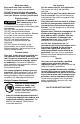
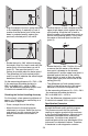
faisceau laser touche le point II sur le mur B tracé auparavant. A 180˚ d B d – Tournez l’appareil de mesure de 180°. Positionnezle de sorte que le milieu du point laser inférieur se trouve sur le point II déjà marqué et le point laser supérieur sur la ligne du plafond. Laissez l’appareil de mesure effectuer un nivellement automatique. Marquez le milieu du point laser supérieur sur la ligne du plafond (point III). – Tournez l’appareil de mesure de 180° sans modifier la hauteur.
CAL (surpassement), les rayons laser continuent à clignoter rapidement jusqu'à ce que l'appareil soit au niveau. Si l'appareil n'est pas au niveau, les rayons laser clignoteront lentement jusqu'à ce que l'appareil atteigne une position au niveau. Pour quitter le mode d'étalonnage, pousser l'interrupteur en position CAL (surpassement) et tenir pendant au moins 5 secondes. Les rayons laser clignoteront rapidement pendant 5 secondes avant de quitter le mode d'étalonnage.
15. Tourner le outil et vérifier la hauteur du rayon avant à nouveau. 16. Répétez les étapes 13 à 15 jusqu'à ce que le rayon avant soit à la mÍme hauteur que les deux rayons latéraux étalonnés, puis passez à l'étape suivante. 17. Insérez et revisser les bouchons d'étalonnage dans le outil. L'étalonnage est terminé. Après avoir quitté le mode d'étalonnage, les rayons laser demeureront immobiles si l'appareil est au niveau ou encore, les rayons clignoteront lentement si l'appareil n'est pas au niveau.
Mise de niveau 8. Mesurez la distance Z à un point plus éloigné du outil et notez-la. Remarque: La précision augmente avec la distance comprise entre les points Y et Z. 9. Comparez les distances Y et Z. B A 10. Si les distances Y et Z sont égales, les deux surfaces sont à l'équerre. Sinon, déplacez les surfaces correspondantes jusqu'à ce que les istances Y et Z soient égales. Mise à l'équerre Nivellement 1. Positionnez le niveau laser outil sur le point le plus élevé de la surface à niveler. 2.
Utiliser avec la fixation Pour fixer l’appareil de mesure sur la fixation multifonctionelle 8, serrez la vis de blocage 9 de la fixation multifonctionelle dans le raccord de trépied 1/4" 6 se trouvant sur l’appareil de mesure. Pour tourner l’appareil de mesure sur la fixation multifonctionelle, desserrez légèrement la vis 9.
GARANTIE LIMITÉE DES PRODUITS LASER ET AUTRES INSTRUMENTS DE MESURE BOSCH Robert Bosch Tool Corporation (le « Vendeur ») garantit à l’acheteur original seulement que tous les produits laser et autres instruments de mesure BOSCH ne comporteront pas de défauts de matériau ou de façon pendant une période de trois (3) ans à compter de la date de l’achat.
Nomas generales de seguridad Lea todas las instrucciones. Si no se siguen todas las instrucciones que ! ADVERTENCIA aparecen a continuación, el resultado podría ser exposición a radiación peligrosa, descargas eléctricas, incendio y/o lesiones graves.
Seguridad en el área de trabajo Mantenga el área de trabajo limpia y bien iluminada. Las áreas desordenadas u oscuras invitan a que se produzcan accidentes. NO utilice la herramienta láser cerca de niĖos ni deje que los niĖos utilicen la herramienta láser. El resultado podría ser lesiones graves en los ojos. Seguridad eléctrica Las baterías pueden explotar ! ADVERTENCIA o tener fugas y causar lesiones o incendios.
Preparación Inserción y cambio de la pila Se recomienda utilizar pilas alcalinas de manganeso en el aparato de medición. Para abrir la tapa del alojamiento de la pila 3 gire el enclavamiento 2 en el sentido de las agujas del reloj a la posición y retire la tapa. Inserte las pilas que se adjuntan. Respete la polaridad indicada en la parte interior del alojamiento de las pilas. Asiente la tapa del alojamiento de las pilas en la parte inferior de la carcasa y empuje la tapa hacia arriba.
Operación Puesta en marcha desconéctelo acto seguido, y vuélvalo a conectar dentro de 4 s. Para confirmar dicha modificación, todos los rayos láser parpadean en rápida secuencia durante 2 s al conectarlo la segunda vez. • Proteja el aparato de medida de la humedad y de la exposición directa al sol. • No exponga el aparato de medición ni a temperaturas extremas ni a cambios bruscos de temperatura. No lo deje, p.ej., en el coche durante un largo tiempo.
Control de la precisión de nivelación horizontal Control de la precisión de nivelación horizontal en el eje longitudinal en el eje transversal de 20 m con un firme consistente y una pared. Para la comprobación se requiere un tramo libre de 20 m sobre un firme consistente con dos paredes A y B. – Coloque el aparato de medición a 20 m de la pared teniéndolo montado en el soporte o un trípode, o bien, depositándolo sobre un firme consistente y plano. Conecte el aparato de medición.
– Variar el nivel de altura del aparato de medida (con el trípode o bien calzándolo) de manera que el centro del haz incida exactamente contra el punto II marcado previamente en la pared B. A 180˚ (punto I). Además, marque el centro del punto láser inferior sobre el suelo (punto II). d B d – Gire 180° el aparato de medición.
5 segundos. Los rayos láser continuarán destellando rápidamente hasta que libere el interruptor de potencia de la posición CAL (anular). Una vez que el interruptor de potencia se ha liberado de la posición CAL (anular), los rayos láser permanecerán en un destello rápido si la unidad está nivelada. Si la unidad está desnivelada, los rayos láser destellarán lentamente hasta que el dispositivo ha alcanzado la posición de nivelación.
13. El objetivo del paso que sigue consiste en ubicar el rayo frontal a la misma altura que la última marca realizada en los pasos anteriores o a la misma altura que los rayos laterales calibrados. Verifique que los rayos láser estén destellando rápidamente, confirmando así que el dispositivo esté nivelado y en modo Calibración. 14. Introduzca la herramienta que se incluye en el puerto de calibración posterior.
personas, puede resultar más sencillo marcar el lugar del haz en una variedad de puntos y, después, generar una línea recta a través de dichos puntos para lograr una línea de nivel. Nivel 3. Mida la distancia A en un punto relativamente cercano al instrumento y tome nota de la distancia. 4. Mida la distancia B en un punto más lejano del instrumento y tome nota de la distancia. Nota: Cuanto mayor sea la distancia entre los dos puntos de medición, mayor será la precisión. 5.
Utilice con Base trípode 6 del aparato de medición con la rosca de 1/4-20 e 5/8-11 del trípode, y sujételo apretando el tornillo de fijación. Para fijar el aparato de medición al base multifuncional 8 enrosque el tornillo de sujeción 9 del base multifuncional en la fijación para trípode de 1/4" 6 del aparato de medición. Para girar el aparato de medición sobre el base multifuncional afloje ligeramente el tornillo 9.
GARANTÍA LIMITADA PARA PRODUCTOS DE HERRAMIENTAS LÁSER Y DE MEDICIÓN BOSCH Robert Bosch Tool Corporation (el "Vendedor") garantiza, únicamente al comprador original, que todos los productos de herramientas láser y de medición BOSCH estarán libres de defectos de material o de fabricación durante un período de tres (3) años a partir de la fecha de compra.