Electric Drives and Controls Hydraulics Linear Motion and Assembly Technologies Rexroth VSB 40.
About this Documentation Title Type of Documentation Document Typecode Internal File Reference Purpose of Documentation Record of Revisions Copyright VSB 40.1 Rexroth VSB 40.1 Project Planning Manual DOK-SUPPL*-VSB*40.1***-PR02-EN-P Document Number 120-2100-B372-02/EN This documentation describes the industrial PC VSB 40.1. Description Release Date Notes 120-2100-B372-01/EN 05.2005 First Edition 120-2100-B372-02/EN 04.
Contents I VSB 40.1 Contents 1 2 System Representation 1-1 1.1 Brief Description VSB 40.1 ........................................................................................................... 1-1 1.2 Operating System ......................................................................................................................... 1-1 1.3 Commissioning .............................................................................................................................
II Contents VSB 40.1 Mounting with Connector Panel on the Top Side .................................................................... 5-4 5.2 Mounting the VSB 40.1, Variant LS.............................................................................................. 5-5 Mounting with Connector Panel in Forward Direction ............................................................. 5-5 5.3 6 Installation Notes ........................................................................................
Contents III VSB 40.1 10 Disposal and Environmental Protection 10-1 10.1 Disposal ...................................................................................................................................... 10-1 Products................................................................................................................................. 10-1 Packaging Materials .............................................................................................................. 10-1 10.
IV Contents VSB 40.1 DOK-SUPPL*-VSB*40.
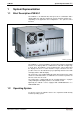
System Representation 1-1 VSB 40.1 1 System Representation 1.1 Brief Description VSB 40.1 The VSB 40.1 is an industrial PC, that represents in combination with a display VDP 16 or VDP 40 a PC-based operator terminal, and that can – depending on the application and configuration – also perform control functions. PST2427_25_RGB.jpg Fig. 1-1: VSB 40.1 The VSB 40.
1-2 System Representation 1.3 VSB 40.1 Commissioning Mount the device properly (for this, see chapter "Dimensions and Installation Notes as of page 5-1). Then, connect the device to the power supply and, if required, to the network. DOK-SUPPL*-VSB*40.
Important Directions for Use 2-1 VSB 40.1 2 Important Directions for Use 2.1 Appropriate Use Introduction Rexroth products represent state-of-the-art developments and manufacturing. They are tested prior to delivery to ensure operating safety and reliability. The products may only be used in the manner that is defined as appropriate. If they are used in an inappropriate manner, then situations can develop that may lead to property damage or injury to personnel.
2-2 Important Directions for Use VSB 40.1 Areas and Use of application The VSB 40.1 by Rexroth is an industrial PC and becomes a PC-based operating terminal when combining it either with a VDP 16 display or VDP 40 display. Depending on the application and configuration, control functionality can be obtained. Note: The VSB 40.1 may only be used with the accessories and parts specified in this document. If a component has not been specifically named, then it may not be either mounted or connected.
Safety Instructions for Electric Drives and Controls 3-1 VSB 40.1 3 Safety Instructions for Electric Drives and Controls 3.1 Introduction Read these instructions before the initial startup of the equipment in order to eliminate the risk of bodily harm or material damage. Follow these safety instructions at all times. Do not attempt to install or start up this equipment without first reading all documentation provided with the product.
3-2 Safety Instructions for Electric Drives and Controls 3.3 VSB 40.
Safety Instructions for Electric Drives and Controls 3-3 VSB 40.1 3.4 General Information • Bosch Rexroth AG is not liable for damages resulting from failure to observe the warnings provided in this documentation. • Read the operating, maintenance and safety instructions in your language before starting up the machine. If you find that you cannot completely understand the documentation for your product, please ask your supplier to clarify.
3-4 Safety Instructions for Electric Drives and Controls VSB 40.1 • Operation is only permitted if the national EMC regulations for the application are met. The instructions for installation in accordance with EMC requirements can be found in the documentation "EMC in Drive and Control Systems". The machine or installation manufacturer is responsible for compliance with the limiting values as prescribed in the national regulations. 3.
Safety Instructions for Electric Drives and Controls 3-5 VSB 40.1 To be observed with electrical drive and filter components: High electrical voltage on the housing! High leakage current! Danger to life, danger of injury by electric shock! DANGER 3.6 ⇒ Connect the electrical equipment, the housings of all electrical units and motors permanently with the safety conductor at the ground points before power is switched on. Look at the connection diagram. This is even necessary for brief tests.
3-6 Safety Instructions for Electric Drives and Controls 3.7 VSB 40.1 Protection Against Dangerous Movements Dangerous movements can be caused by faulty control of the connected motors.
Safety Instructions for Electric Drives and Controls 3-7 VSB 40.
3-8 Safety Instructions for Electric Drives and Controls 3.9 VSB 40.1 Protection Against Contact with Hot Parts Housing surfaces could be extremely hot! Danger of injury! Danger of burns! CAUTION ⇒ Do not touch housing surfaces near sources of heat! Danger of burns! ⇒ After switching the equipment off, wait at least ten (10) minutes to allow it to cool down before touching it. ⇒ Do not touch hot parts of the equipment, such as housings with integrated heat sinks and resistors. Danger of burns! 3.
Safety Instructions for Electric Drives and Controls 3-9 VSB 40.1 3.11 Battery Safety Batteries contain reactive chemicals in a solid housing. Inappropriate handling may result in injuries or material damage. Risk of injury by incorrect handling! CAUTION Note: ⇒ Do not attempt to reactivate discharged batteries by heating or other methods (danger of explosion and cauterization). ⇒ Never charge non-chargeable batteries (danger of leakage and explosion). ⇒ Never throw batteries into a fire.
3-10 Safety Instructions for Electric Drives and Controls VSB 40.1 Notes DOK-SUPPL*-VSB*40.
Technical Data 4-1 VSB 40.1 4 Technical Data 4.1 PC Box PC box Type E Celeron with minimum 2 GHz Processor Integrated graphic controller with maximum 8 MB video memory Chip set 512 MB / 1024 MB Random access memory (RAM) Min.
4-2 Technical Data 4.2 VSB 40.1 Power Supply 115 V / 230 V Nominal input voltage: 115 VAC / 230 VAC Input voltage range: 90 ... 264 VAC Input current: 2.5 A for nominal voltage 230 VAC 5.0 A for nominal voltage 115 VAC Inrush current: 100 A for 264 VAC Output voltages: Current Tolerances Min. Max. +3.3 V +5 V +12 V –12 V +5 V SB 0,5 A 0,5 A 1,0 A 0A 0A 20 A 25 A 17 A 0.8 A 2.0 A Max. Output power: 250 W* Efficiency (under full load): 0.73 for 115 VAC, 0.
Technical Data 4-3 VSB 40.1 4.4 Ambient Conditions In operation Storage / Transport +5 °C... +45 °C -20 °C to +60 °C +0 °C ... +40 °C +0 °C ... +40 °C Max. temperature gradient Temperature change up to 3°C per minute Not defined Relative humidity Climatic class 3K3 according to EN 60721, condensation not permissible. Climatic class 3K3 according to EN 60721, condensation not permissible. Air pressure Up to 2 000 m above MSL according to DIN 60204 Mechanical strength Max.
4-4 Technical Data UL/CSA certification VSB 40.1 The devices of the VSB family are basically certified according to • UL508 (Industrial Control Equipment) and • C22.2 No. 142-M1987 (CSA) However, it is possible that there are combinations or extension stages with restricted or missing certification. Thus, verify the registration according to the UL marking on the device.
Technical Data 4-5 VSB 40.1 4.7 Compatibility Check All Rexroth controls and drives are developed and tested according to the latest state-of-the-art. As it is impossible to follow the continuing development of all materials (e. g. lubricants in machine tools) which may interact with our controls and drives, it cannot be completely ruled out that any reactions with the materials used by Bosch Rexroth might occur. Therefore, test new lubricants, cleaning agents, etc.
4-6 Technical Data VSB 40.1 DOK-SUPPL*-VSB*40.
Dimensions and Installation Notes 5-1 VSB 40.1 5 Dimensions and Installation Notes To meet the various installation requirements, the VSB 40.1 equipped with an optional drive is available as different variants. Depending on the provided clearance for the opening drive, select the VSB 40.1 as variant NN (see Fig. 5-1) or as variant LS (see Fig. 5-1) with the drive in connector direction (position 12 of type code on page 11-1). For safe mounting of the VSB 40.1 in variant NN, e. g.
5-2 Dimensions and Installation Notes 5.1 VSB 40.1 Mounting the VSB 40.1, Variant NN Horizontal Mounting with Connector Panel in Forward Direction Foto_Anschluesse_vorne.tif Fig. 5-3: Connector panel in forward direction, optional drive at the top g hole) - mountin 80 (distance mounting hole) 183 (outer dimension) 51,5 nce 350 (dista 26 6,8 2 (o ut er di m n) en r dimensio 364 (oute sio n) Massbild_1_3d.FH9 Fig.
Dimensions and Installation Notes 5-3 VSB 40.1 Vertical Mounting with Connector Panel in Forward Direction Foto_Anschluesse_vorne_vertikal.tif Fig. 5-5: Vertical Mounting with Connector Panel in Forward Direction 80 (Distance mounting holes) S1 S2 XCOM XMS XUSB XLAN XLPT XVGA PWR A0 X71 XDPSLAVE A1 350 (Distance mounting hole) A2 A3 A4 A5 A6 80 16 (Distance mounting holes) Ø6.8 16 80 (Distance mounting holes) 52.7 80 (Distance mounting holes) 186.
5-4 Dimensions and Installation Notes VSB 40.1 Mounting with Connector Panel on the Top Side Foto_Anschluesse_oben.tif Fig. 5-7: Connector panel on the top side, optional drive in forward direction ce - istan (distance mounting hole) 262 (outer dimension) 80 (d 350 le) g ho ntin mou 81 6,8 18 3( ou ter 364 dim (o on) ensi dim uter en sio n) Massbild_2_3d.FH9 Fig. 5-8: Dimensions when mounting the connector panel on the top side DOK-SUPPL*-VSB*40.
Dimensions and Installation Notes 5-5 VSB 40.1 5.2 Mounting the VSB 40.1, Variant LS Mounting with Connector Panel in Forward Direction Foto_Anschluesse_LS.jpg Fig. 5-9: Mounting with connector panel in forward direction nsion) ter dime 364 (ou ounting nce - m 40 (dista 81 (distamce mounting hole) 208 (outer dimension) 49,5 3 hole) 26 2 (o ut er dim en sio n) Massbild_3_3d.FH9 Fig. 5-10: DOK-SUPPL*-VSB*40.
5-6 Dimensions and Installation Notes 5.3 VSB 40.1 Installation Notes • Avoid installation locations exposed to direct sunlight, as additional heat development can occur. • When determining installation location and mounting position observe, that the optionally available drive can be opened unobstructed. • Install the VSB in a manner ensuring easy access to the connector panel. • Provide a sufficient clearance of 50 mm (on all sides) for cooling and cable routing behind the device.
Display and Operating Components 6-1 VSB 40.1 6 Display and Operating Components 6.1 Power Button Besides the connector panel (see Fig. 7-1) a button labeled with "PWR" is provided. Usually, this power button has no function, as the VSB 40.1 is started by applying the supply voltage. This is preset in BIOS. If the BIOS setting has been modified by accident, the VSB 40.1 can be started by pressing this button. To reset the original status, in which the VSB 40.
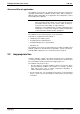
6-2 Display and Operating Components Activation of the VDP or the external monitor VSB 40.1 If required, you can select, if the VDP connected with the G4 display interface, the external monitor operated at the VGA connection or both can be addressed: 1. Select "Intel(R) Extreme Graphics" in the task bar. Graphics.bmp Fig. 6-1: Intel Extreme Graphics 2. Chose "Graphics Options" -> "Graphics Properties". Grafikeigenschaften.bmp Fig. 6-2: Graphics Properties 3. The "Intel ...
Display and Operating Components 6-3 VSB 40.1 4. If an external monitor is connected, you can select on the left side by clicking on the corresponding icons, if you want to address only the external monitor (select "Monitor"), only the screen of the connected VDPs (select "Notebook") or both screens (select "Intel(R) Dual Display Clone"). 5. After confirming using , another window opens where the selection is to be reconfirmed by pressing . Otherwise, the monitor selection is not applied.
6-4 Display and Operating Components VSB 40.1 RegisterTasten.bmp Fig. 6-5: “Hot Keys“ DOK-SUPPL*-VSB*40.
PC Box 7-1 VSB 40.1 7 PC Box 7.1 View on the Connector Panel X71 XMS XLAN XKB XLAN XMS XUSB XCOM XLPT XLPT XVGA XKB XCOM XVGA XUSB VSB_Anschlüsse.FH11 Fig. 7-1: DOK-SUPPL*-VSB*40.
7-2 PC Box 7.2 VSB 40.1 Interfaces Note: Malfunctions caused by insufficient shielding! Use only shielded cables and metallic/conductive connector or coupling covers with large-area screen contact. Overview Des.
PC Box 7-3 VSB 40.1 Serial Interface XCOM XCOM - Serial interface A serial standard interface is provided at connection XCOM. D-Sub male connector, 9-pin Type: RS232 Cable length: 15 m max. Cable type: Shielded, cross section min. 0.14 mm² Transmission rate: Max.
7-4 PC Box VSB 40.1 Parallel Interface XLPT XLPT – Parallel Interface for Printer, Scanner, etc. D-Sub female connector, 25-pin Type: SPP (ex works), EPP, ECP Cable length: 3 m max. Cable type: Shielded, cross section min. 0.14 mm² Interrupt (IRQ): 7 I/O address: AUTO or 378H (recommended) XLPT Interface mode EPP 1 13 14 25 max. 3m SPP Write STROBE Data0 Data0 Data1 Data1 Data2 Data2 Data3 Data3 Data4 Data4 Data5 Data5 Data6 Data6 Data7 Data7 Intr ACK Wait BUSY n.
PC Box 7-5 VSB 40.1 XUSB Interfaces XUSB – serial interfaces for printer, scanner, CD-ROM drive The devices feature two USB interfaces on the connector panel (XUSB). These interfaces are compatible to USB 1.1 and USB 2.0. Note: The maximum power consumption of the connected devices must not exceed 500 mA. If the load exceeds 500 mA, the internal current monitoring is activated.
7-6 PC Box VSB 40.1 Ethernet Interface XLAN XLAN – Network Connection The industrial PC can be connected with an Ethernet network via an Ethernet interface XLAN. RJ45 female connector, 8-pin Type: Ethernet 10Base T / 100Base X Cable length: 100 m max. Cable type: Shielded, twisted pair Transmission rate: 10 or 100 Mbits/s max. 100 m 1 XLAN, RJ45 2 To the network 3 8 4 5 1 6 7 8 Ethernet_sst.cdr Fig.
PC Box 7-7 VSB 40.1 max. 1,5 m RED GREEN BLUE ID2 GND XVGA RED GND 1 GREEN GND BLUE GND 15 Digital GND ID0 ID1 Hsync Vsync ID3 1 2 3 4 5 6 Display 7 8 9 10 11 12 13 14 15 Shield applied to the metal housing of the plug-in connector Vga_sst.cdr Fig. 7-7: VGA interface Setting incorrect resolutions and colors may destroy your monitor! ⇒ CAUTION! Please observe the technical data of your monitor and adapt the operating system parameters accordingly.
7-8 PC Box VSB 40.1 Keyboard Interface XKB XKB – PS/2 Mini DIN Keyboard / Mouse Interface PS/2 Mini DIN female connector, 6pin Cable length: 1.5 m max. Cable type: Shielded, cross section min. 0.14 mm² max. 1.5 m XKB Keyboard Data Mouse Data 5 6 4 2 Power, +5VDC 1 Keyboard Clock Shield 2 Keyboard 3 GND 3 1 Mouse Clock 4 5 6 Shield applied to the metal housing of the plug-in connector Tastatur_sst.FH9 Fig.
PC Box 7-9 VSB 40.1 after completed startup, because the mouse initialization occurs during the booting process. Note: The connected mouse must be PS/2-compatible. Normally, the BIOS reserves IRQ 12 for the PS/2 mouse. If there are address conflicts, e. g., if IRQ 12 has already been used by another PC extension card, you should change the IRQ of this extension card to another IRQ, that is still not-assigned. Note: If a VDP display is connected to a VSB 40, the mouse can only be connected to this one.
7-10 PC Box VSB 40.1 PC Power Supply 24 VDC Power Supply This screw connection is used for device variants for 24 VDC. All internally required voltages are generated from the 24 VDC supply. Anschluss24V.jpg Fig. 7-10: Connection terminal for the 24 VDC supply Note: Only copper wire is to be used to connect these terminals. Tighten the screws of the screw terminals with a torque of 0.4 Nm (1.81 kg in). Parameters Value Input voltage UN 24 VDC ; (19 ...
PC Box 7-11 VSB 40.1 Danger without protective separation! ⇒ DANGER ⇒ The 24 VDC input voltage must comply with the requirements of the "Protective separation". Plug and unplug the connector only in no-voltage condition! L1 L2 L3 400V + 5% 400V 400V - 5% PE 0V + 24V Sichertrafo.cdr Fig.
7-12 PC Box PE L3 L2 L1 VSB 40.1 PE 102 (green/yellow) Power supply with safety transformer acc. to EN 60742 24 VDC Cross-sections depending on current consumption, min. of 4 mm 2 . For higher current con- 2 sumption use 2 x 4 mm . 62 (1)(blue) Length max. 4 m A B A 102 (green/yellow) (2) 24 V load Earth bar 0 V load A = Terminal block 42 B = Terminal block 10 2 : Terminals in isolated arrangement VSB 40.1 (24 VDC version) Cross sections depending on current consumption, but a min. of 0.
PC Box 7-13 VSB 40.1 230/115 VAC Power Supply This connection is used for device variants for 230/115 VAC. All internally required voltages are generated by the 230/115 VAC power supply unit. CAUTION The supply voltage must comply with overvoltage category II! Otherwise the integrated power supply unit might be destructed. ⇒ Use an isolating transformer to generate the 230/115 VAC (see following page).
7-14 PC Box VSB 40.1 Incoming mains L1 L2 L3 N PE Min.162 (green/yellow) To machine 62 (green/yellow) All housing components (PE bolt) PE PE PE PE PE N W1 V1 102 (green/yellow) U1 To control cabinet housing 162 (green/yellow) PE terminal bar for 0 V wiring (see fig.
PC Box 7-15 VSB 40.1 7.3 Optional Serial Interfaces According to the configuration, serial interfaces are available for the extension cards A5 and A6 on the slots. The interfaces have different pin assignments and signal assignments. Before using the interfaces, identify the type assignment or pin assignment, see the configuration sticker on the device (CFG-VSN01E1xx-xx-xx-xx-xx-xx).
7-16 PC Box VSB 40.1 CFG-VSN01E1-NN-NN-NN-NN-S3-S3 Serial Interface RS232 XCOM3 on Slot for Extension Card A5 Pin Assignment 1 DCD (Data Carrier Detect) 2 RX (Receive Data) 3 TX (Transmit Data) 4 DTR (Data Terminal Ready) 5 Signal Ground 6 DSR (Data Set Ready) 7 RTS (Request to Send) 8 CTS (Clear to Send) 9 RI (Ring Indicator) Fig.
PC Box 7-17 VSB 40.1 CFG-VSN01E1-NN-NN-NN-NN-NN-S2 Serial Interfaces RS232 and RS422 XCOM4 on Slot for Extension Card A6 Pin Assignment 1 DCD (Data Carrier Detect) 2 RX (Receive Data) 3 TX (Transmit Data) 4 DTR (Data Terminal Ready) 5 Signal Ground 6 DSR (Data Set Ready) 7 RTS (Request to Send) 8 CTS (Clear to Send) 9 RI (Ring Indicator) Fig.
7-18 PC Box VSB 40.1 Jumper Setting on Motherboard XCOM3 Jumper JPB2 Jumper JPB1 XCOM4 XCOM3 XCOM4 Jumper JPB1 Motherbord 1070922809 Jumper JPB2 Motherbord 1070923827 Lage_der_Anschlusse_auf_den_Motherbord-Varianten.FH11 Fig.
PC Box 7-19 VSB 40.1 CFG-VSN01E1-NN-NN-NN-NN-NN-S6 Serial Interfaces RS232 and RS422 (Rexroth Standard) XCOM4 on Slot for Extension Card A6 Pin Assignment 1 DCD (Data Carrier Detect) 2 RX (Receive Data) 3 TX (Transmit Data) 4 DTR (Data Terminal Ready) 5 Signal Ground 6 DSR (Data Set Ready) 7 RTS (Request to Send) 8 CTS (Clear to Send) 9 RI (Ring Indicator) Fig.
7-20 PC Box VSB 40.1 Note: There is no uniform and standard pin assignment for RS422. When connecting RS422 devices, the pinout in the documentation is always to be considered. Jumper Setting on Motherboard XCOM3 Jumper JPB2 Jumper JPB1 XCOM4 XCOM3 XCOM4 Jumper JPB1 Motherbord 1070922809 Jumper JPB2 Motherbord 1070923827 Lage_der_Anschlusse_auf_den_Motherbord-Varianten.FH11 Fig.
Maintenance and Installation 8-1 VSB 40.1 8 Maintenance and Installation 8.1 General Information VSB-type industrial PCs are maintenance-free. However, some components are subject to wear and must be replaced (see chapter "Wear parts" on page 4-4). Maintenance Include the following measures in the maintenance schedule: • At least once a year, check all plug and terminal connections for proper tightness and damage. Check that cables are not broken or crushed. Replace damaged parts immediately.
8-2 Maintenance and Installation 8.3 VSB 40.1 Connection of the Uninterruptibe Power Supply The accessories of Bosch Rexroth include uninterruptible power supplies (UPS) for the 230 V supply as well as for the 24 V supply (see section "Accessories" on page 11-2). These USP devices bridge short voltage dips. Longer voltage dips cause and allow a normal shutdown of the operating system. Therefore, Bosch Rexroth recommends to use an UPS.
Maintenance and Installation 8-3 VSB 40.1 Dimensions of the UPS USV_Montagemasse.eps Fig. 8-3: Installation dimensions UPS holder The depth of the UPS holder without mounting rail adapter is 117.5 mm and with mounting rail adapter 127 mm. 8.4 Hard disk The installation frame of the hard disk can be accessed from the rear side of the VSB 40.1 or for variant LS from the bottom side of VSB 40.1.
8-4 Maintenance and Installation Note: VSB 40.1 The hard disk to be inserted must already have an installed operating system, if no external boot medium is connected to the industrial PC. In any case, it is recommended to have a completely installed operating system on the hard disk, to shorten the installation time! The change of the hard disk for the two variants is not identic, as the hard disk is located at different positions. Changing the Hard Disk of the VSB 40.1, Variant NN 1.
Maintenance and Installation 8-5 VSB 40.1 7. Loosen the fastening screws of the hard disk frame. The hard disk and (depending on the device design) the CD DVD drive are mounted on this plate: 83_Laufwerk2.JPG Fig. 8-5: Fastening screws of the hard disk frame 8. Lift the hard disk frame: 83_offen.JPG Fig. 8-6: Lifted hard disk frame 9. Loosen the two cables (IDE and power supply) from the hard disk. 10. Now, remove the old and insert the new hard disk. 11. Connect the two cables.
8-6 Maintenance and Installation VSB 40.1 16. After a regular booting of the PC, the user data as well as the operating system settings for the normal operating mode are to be restored. Changing the Hard Disk of the VSB 40.1, Variant LS 1. Save all required user data as well as the operating system settings of your system on an external storage medium or via the network connection! 2. Shutdown the operating system. 3. Wait until the power supply unit switches off and then, switch off the supply voltage.
Maintenance and Installation 8-7 VSB 40.1 7. Tip the VSB 40.1 to the left side. 83_LS_gekippt.JPG Fig. 8-9: Tip the VSB 40.1 to the left and remove it from the mounting plate 8. Now, you can loosen the cables (IDE and power supply) from the hard disk and put the VSB 40.1 on its left side. If necessary, you must loosen the cables from the CD-DVD drive to be able to position the VSB 40.1. 83_LS_offen2.JPG Fig. 8-10: DOK-SUPPL*-VSB*40.
8-8 Maintenance and Installation VSB 40.1 9. Loosen the screws, with which the hard disk is mounted, with a Philips screwdriver by inserting it through the holes in the mounting frame. 83_LS_Schrauber.JPG Fig. 8-11: Loosen the fastening screws of the hard disk 10. Remove the old and insert the new hard disk. 11. Plug-in the cables at the hard disk and, if necessary, at the CD/DVD drive. Observe that you don't bend the connection pins.
Maintenance and Installation 8-9 VSB 40.1 Exchanging Hard Disk with Damper In case of VSB devices containing hard disks with damper, the hard disk is located below the device, refer to Fig. 8-12. Position_der_schwingungsgedaempften_Festplatte.EPS Fig. 8-12: Location of the hard disk with damper In order to exchange the hard disk, remove the fastening screw of the hard disk installation frame on the bottom side of the VSB 40.1 (refer to Fig. 8-13).
8-10 Maintenance and Installation 8.5 VSB 40.1 Extension Cards To plug extension cards slots for the PCI bus are available.
Maintenance and Installation 8-11 VSB 40.1 5. Lift up the cover with the fan. 84_Deckeloffen.JPG Fig. 8-15: Lift the cover with fan 6. Loosen the fastening screw of the corresponding extension card and remove it: 84_Slotblech2.JPG Fig. 8-16: Remove extension card 7. Insert the plug-in assembly from the top. Don't use force. The connections are to be inserted in the plug on the main board. DOK-SUPPL*-VSB*40.
8-12 Maintenance and Installation VSB 40.1 8. Fasten the plug-in assembly with the screw, with which the extension card was fixed. 84_neueKarte2.JPG Fig. 8-17: Fix the new PCI card with the screw 9. Close the top cover and fasten it with the two screws. If the card is equipped with a Plug and Play (PnP) function, it is automatically recognized by the operating system and integrated in the system, provided that no hardware conflicts (IRQ etc.) with other extension cards or connected devices occur.
Software 9-1 VSB 40.1 9 Software 9.1 UPS Software The software required for the optionally available UPS (see chapter 8.3 "Connection of the Uninterruptible Power Supply" on page 8-2 and section chapter "Uninterruptible Power Supply" on page 11-2) is stored on the hard disk of the VSB 40.1. Before being able to use this software, you have to install it. Install this software using the installation softaware BRCVInstall saved on the desktop. 9.
9-2 Software VSB 40.1 The following dialog window appears for the different settings: UPDD_settings.bmp Fig. 9-2: Dialog window to set the touch screen For more detailled information, please select the Help button on the respective tab. Via "Start -> Programs -> UPDD" you reach further useful programs, if required. The program “Calibrate” might be of special interest. If required, you can calibrate the touch mouse with the help of this program.
Disposal and Environmental Protection 10-1 VSB 40.1 10 Disposal and Environmental Protection 10.1 Disposal Products Our products can be returned to us free of charge for disposal. However, it is a precondition that the products are free of oil, grease or other dirt. Furthermore, the products returned for disposal must not contain any undue foreign matter or foreign component. Please send the products free domicile to the following address: Bosch Rexroth AG Electric Drives and Controls Bürgermeister-Dr.
10-2 Disposal and Environmental Protection VSB 40.1 Recycling Due to their high content of metal most of the product components can be recycled. In order to recycle the metal in the best possible way, the products must be disassembled into individual modules. Metals contained in electric and electronic modules can also be recycled by means of special separation processes. The synthetic materials remaining after these processes can be thermally recycled.
Ordering Information 11-1 VSB 40.1 11 Ordering Information 11.1 Type Code Designation VSB40.1 According to the following type code designation, the IPC VSB 40.1 is available in different variants. Abbrev. column 1 2 3 1 2 3 4 5 6 7 8 9 0 1 2 3 4 5 6 7 8 9 0 1 2 3 4 5 6 7 8 9 0 1 2 3 4 Example: V S B 4 0 . 1 G 4 E - 5 1 2 N N - C 1 C - A D - N N - F W Product VSB. . . . . . . . = VSB Line 40 . . . . . . . . . . . . . . . = 40 Design 1......................=1 Control panel interface GIGASTAR . . . . . .
11-2 Ordering Information VSB 40.1 11.2 Accessories Network Connection Ordering designation Part number Description B-AC STECKER NETZ 230V 1070 912881 Mains connector 230 V, male inlet connector for nonheating apparatus, angular, for self-mounting BKS-U-N-NTZKAB-IPCRHO-002,5-P 1070 048937 Mains cable 230 V with female inlet connector for nonheating apparatus, angular, cable length 2.5 m Fig. 11-2: Connectors and cables for VSB 40.
List of Figures 12-1 VSB 40.1 12 List of Figures Fig. 1-1: VSB 40.1 1-1 Fig. 3-1: Hazard classification (according to ANSI Z535) 3-1 Fig. 4-1: Technical data: PC box 4-1 Fig. 4-2: Technical data of the power supply unit 115 V / 230 V 4-2 Fig. 4-3: Technical data of the power supply unit 24 V 4-2 Fig. 4-4: Ambient conditions 4-3 Fig. 4-5: Used standards 4-3 Fig. 4-6: Typical operating and storage conditions of the hard disk 4-4 Fig. 4-7: Service life of the fan 4-4 Fig. 5-1: VSB 40.
12-2 List of Figures VSB 40.1 Fig. 7-15:Pin assignment of the 230/115 VAC connection X20 7-13 Fig. 7-16:Technical data 115/230 VAC connection 7-13 Fig. 7-17:Voltage connection 230 VAC via isolating transformer 7-14 Fig. 7-18:Pin assignment RS232, D-sub male connector, 9-pin 7-15 Fig. 7-19:Serial interface adapter XCOM4 on slot for extension card A6 715 Fig. 7-20:Pin assignment RS232, D-sub male connector, 9-pin 7-16 Fig. 7-21:Pin assignment RS232, D-sub male connector, 9-pin 7-16 Fig.
List of Figures 12-3 VSB 40.1 Fig. 11-2:Connectors and cables for VSB 40.1 11-2 Fig. 11-3:Connecting cables to the VDP 16.1, VDP 40.1 and VDP 60.1 11-2 Fig. 11-4:Uninterruptible power supply 11-2 DOK-SUPPL*-VSB*40.
12-4 List of Figures VSB 40.1 DOK-SUPPL*-VSB*40.
Index 13-1 VSB 40.
13-2 Index VSB 40.
Index 13-3 VSB 40.
13-4 Index VSB 40.1 DOK-SUPPL*-VSB*40.
Service and Support 14-1 VSB 40.1 14 Service and Support 14.1 Helpdesk Our service helpdesk at our headquarters in Lohr, Germany, will assist you with all kinds of inquiries. Contact us: • By phone through the Service Call Entry Center Monday to Friday: 7:00 am – 6:00 pm CET +49 (0) 9352 40 50 60 • By fax +49 (0) 9352 40 49 41 • By E-mail: service.svc@boschrexroth.de 14.
14-2 Service and Support VSB 40.1 DOK-SUPPL*-VSB*40.
Bosch Rexroth AG Electric Drives and Controls P.O. Box 13 57 97803 Lohr, Germany Bgm.-Dr.-Nebel-Str. 2 97816 Lohr, Germany Phone +49 (0)93 52-40-50 60 Fax +49 (0)93 52-40-49 41 service.svc@boschrexroth.de www.boschrexroth.com R911310079 Printed in Germany DOK-SUPPL*-VSB*40.