
User's Manual


DS840LSN | Installation Guide | 4. Wiring EN | 5
Bosch Security Systems | 9/03 | PRELIMINARY 4998132113Ar11
4. Wiring
Apply power ONLY after all connections
have been made and inspected. Do NOT
coil excess wiring inside the detector.
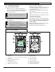
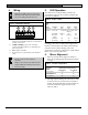
Figure 5: DS840LSN Terminals
1 2 3 4
1 - aLSN1 & bLSN1: coming from the preceding
LSN element. Shielded cable is recommended
for bus connections
2 - aLSN2 & bLSN2: going to the next LSN
element. Shielded cable is recommended for
bus connections.
3 - 5 & 6: Spare terminals.
4 - 7: Connection for ground wire from shielded
cable.
Do not coil excess wire inside the
enclosure.
Plug the wire entrance hole with the foam
plug provided after all wiring connections
have been made.
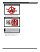
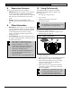
5. LED Operation
The detector uses 3 colored LEDs to indicate the
various alarm and supervision trouble conditions that
that exist. See Table 2.
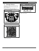
Table 2: Status of LEDs
Walk
Test
Status Condition Red Yellow Green
Disabled All Off Off Off
Power-Up Sequential Green, Yellow, Red
Flashing
Dual Alarm Flashing Off Off
Microwave
Alarm
Off Flashing Off
PIR Alarm Off Off Flashing
Enabled
No Activity Off Off Off
During walk testing, the LEDs light for the first
technology (microwave or PIR) and then light red to
indicate a detector alarm. The LEDs will not indicate
activation of the second technology with color.
If the detector experiences a Microwave or PIR self-test
failure, it is in need of replacement.
6. Mirror Alignment
1. Select the vertical mirror angle from Table 3 to
match the mounting height and desired maximum
coverage.
Table 3: Broad Coverage Mirror
Maximum Coverage DistanceMounting
Height
7.5 m (25 ft.) 12 m (40 ft.)
2.0 m (6.5 ft.)
-6° * -4° *
2.3 m (7.4 ft.)
-10° -8°
2.6 m (8.5 ft.)
-12° -8°
* = Required Settings for Pet Applications
2. The angle adjust markings are on the mirror. Push
in on the bottom or top of the mirror assembly to
position the angle hash marks with the markers on
each side of the frame (Figure 6) based on the
values in Table 3.