
User's Manual


DS840LSN | Installation Guide | 11. Coverage Patterns EN | 8
Bosch Security Systems | 9/03 | PRELIMINARY 4998132113Ar11
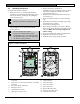
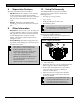
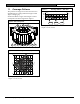
11. Coverage Patterns
The protected coverage area is where the microwave
and PIR patterns overlap (indicated in Figure 10 and
Figure 11 in light gray).
Numbered callouts in Figure 10 and Figure 11 below
correspond to the mirror segments in Figure 9.
Figure 9: Mirror Segments
1 2 3 4 5 6 7 8 9
10
15
11
16
12
13
17
14
Figure 10: Coverage Pattern – Top View
0
Meters
0
Feet
40
12
0
F
e
e
t
20
20
6
6
M
e
t
e
r
s
0
8
9
6
7
5
3
4
10
14
1
2
3
4
5
6
7
8
9
10
11
12
13
14
15
17
16
Coverage patterns are based on a detector mounting
height of 2.0 m (6.5 ft.)t
Figure 11: Coverage Pattern – Side View
0
12
40
Meters
0
10
F
e
e
t
0
Feet
M
e
t
e
r
s
0
3
2
6.5
15-17 10-14 1-9
Coverage patterns are based on a detector mounting
height of 2.0 m (6.5 ft.)t