Model 2472AA Long Range, Moderate Power Wireless CPE/Outdoor Bridge Instruction Manual Telex Communications, Inc. 8601 East Cornhusker Hwy, Lincoln, NE 68505 Rev.
COPYRIGHT & TRADEMARKS Copyright @ 2003 Telex Communications, Inc., All Rights Reserved. Microsoft, Windows, and the Windows logo are registered trademarks of Microsoft Corporation. All other trademarks and brand names are the property of their respective proprietors. TELEX LIMITED WARRANTY Uniform Limited Warranty: Telex branded products are warranted by Telex Communications, Inc.
FCC STATEMENT This Wireless CPE has been tested and complies with the specifications for a Class B digital device, pursuant to Part 15 of the FCC Rules. These limits are designed to provide reasonable protection against harmful interference in a residential installation. This equipment generates, uses, and can radiate radio frequency energy and, if not installed and used according to the instructions, may cause harmful interference to radio communications.
Table of Contents Warranty & Copyright Information FCC Statement Chapter 1: Introduction 2 3 6 The Telex Wireless CPE/Outdoor Bridge Features Package Contents Chapter 2: Getting to Know the Wireless CPE 6 7 8 9 Inside the Wireless CPE The Power-Over-Ethernet Injector The Rear Panel LED’s 9 10 11 Chapter 3: Installing the Wireless CPE 12 Selecting a Mounting Location Attaching the Mounting Bracket and Aiming Routing the CAT5 cable Connecting the Wireless CPE 12 13 14 14 Chapter 4: Configuring the
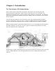
Chapter 1: Introduction The Telex Wireless CPE/Outdoor Bridge Perfect for the home or small office connection to the network, the Telex Wireless CPE (Customer Premise Equipment) extends wireless connectivity from an access point to any Ethernet-ready network device, such as a switch, router, desktop or notebook PC. The Wireless CPE simply and efficiently transmits data between 10Base-T and your wireless LAN or wireless ISP access point.
Features • • • • • • • • • • • An All- in-One Wireless Solution for any Ethernet-Ready Network Device Easy IE and Netscape Web browser configuration, no additional drivers needed Interoperable with 802.11b (DSSS) 2.4 GHz Equipment, Prism 2.5 based Up to 11 Mbps High-Speed Data Rate, Throughput up to 5.
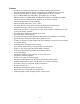
Package Contents PoE Injector 12V Power Supply 7’ Cat5 Cable Telex CPE Angle Bracket Hardware pack CD & Quick Guide Tools and Hardware Needed: The following tools will be needed to assemble and mount your wireless CPE: 7/16” nut driver or wrench 5/16” nut driver or wrench 3/4” wrench or adjustable wrench for grommet nut UV-stable plastic cable ties or black electricians tape Mast pipe or DSS dish mount on which to mount the CPE Adequate length of exterior CAT-5 cable RJ45 plugs and crimping tool 7
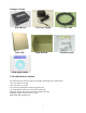
Chapter 2: Getting to Know the Wireless CPE Inside the Wireless CPE Before you can either test or install the Telex Wireless CPE, you must attach a length of outdoorrated (external) CAT-5 Ethernet cable to the unit. Remove the access panel from the rear panel of the CPE using a 5/16” nut driver or wrench. Loosen the plastic nut on the outside of the waterproof cable entry grommet, then insert the unterminated end of a length of exterior CAT-5 8-conductor Ethernet cable through this grommet.
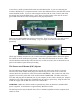
You will see a small 2-position slide switch near the RJ45 socket. If you are connecting the wireless CPE directly to a computer network card or other Ethernet device, then slide this switch toward the RJ45 socket. If you are connecting the wireless CPE to a hub or switch, then slide this switch away from the RJ45 socket. Later, when you apply power to the unit, the second green LED will indicate if this switch position was properly selected.
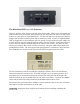
The Rear Panel LED’s (v 1.2.5 firmware) There are 4 LED’s visible from the rear side of the wireless CPE. These can be seen through the small window in the access panel. When powered-up, the first green LED will be lit ONLY if the PoE box is connected to an active Ethernet port. If it does not light, then check that all cables are plugged into the PoE box and the power strip is turned on (if used).
Chapter 3: Installing the Wireless CPE Selecting a Mounting Location It is very important to position the CPE to ensure the highest possible data transfer speed in all kinds of weather and in all seasons. The wireless CPE operates on a radio frequency of 2.4 GHz and must be line-of-sight (LOS) with the access point (AP) or other CPE if in Ad-Hoc mode. Hills, buildings, trees and large vehicles must not block the signal path.
If attaching the wireless CPE to a mast, pipe or DSS dis h- mount, then attach the angle bracket to the mast as shown, using the U-bolts, nuts, washers and serrated clamps from the parts bag. If possible, sight along the top of the angle bracket to aim the wireless CPE in the correct direction. If you are using a vertical mast and require upward or downward beam tilt to the AP, then use the optional holes in the angle bracket to obtain a 10 degree tilt, either up or down.
Routing the CAT-5 cable When you have completed aiming and securing the CPE to the mount, attach and secure the CAT-5 cable to the mounting pipe or other support using tie wraps or black electrical tape. Secure the CAT-5 cable to the outside wall of the building using cable clamps and wood screws or other suitable hardware. It is advisable to place a CAT-5 Surge Arrestor in series with the cable before it enters the building.
WARNING: Make sure that the front of the antenna is pointed away from any humans or animals while power is applied! A safe distance is approximately 10 inches or more. The rear side of the CPE is always safe. The PoE injector box may be placed on the floor or mounted anywhere near the computer, hub, switch or router. There are 4 LED’s visible from the rear side of the wireless CPE. These can be seen through the small window in the access panel.
Chapter 4: Configuring the Wireless CPE Overview The Telex wireless CPE is shipped with default (factory-set) values for certain network settings. You will need to change these settings at the client location to match those provided by your ISP or IS Department. To do this requires 3 main steps: 1. Change your computer network settings to match the default network settings in the CPE so your computer can communicate with the CPE. 2. Using a standard web browser (Internet Explorer 5.5 or later, Netscape 7.
Step 1: Change your computer network settings a. Enable TCP/IP networking on your PC if you have not already done so, then right-click (use the right mouse button) on the Network (My Network Places) icon on your computer’s desktop and select Properties from the pop-up menu. b. Right-click on Local Area Connections and select Properties from the pop-up menu. c. Click on the installed TCP/IP protocol, then click Properties. d. Enter the following settings: IP Address: 192.168.1.100 Subnet Mask: 255.255.255.
System Status The following page should be displayed if no access points are available. Make sure that the Firmware Version is current (see Chapter 7). Check the Telex website occasionally to check for updates. Select the Wireless Scan page to show available access points and their channel, signal level and BSS Mode (including WEP). Press the Refresh button to update. If your network SSID is shown in the Scan (e.g. wlandemo), the n click on it to automatically associate the CPE to this AP.
Click on Magnify in New Window to open a large font window for use in antenna aiming. This window automatically updates every few seconds. It should look like this: The Ethernet Clients page will show all computers currently wired to this CPE.
Configuration To enter the SSID, Channel, Transmission Rate, Access Point Density or RTS information manually, select the Wireless screen as shown below. For information on any selection, press the Help page tab. Make any changes you require, then click Save. To use standard WEP security, select the Security page tab shown below and select WEP enabled. Choose from either 64 or 128 bit WEP Key Length, then enter the pass phrase. Make sure that your access point uses the same WEP information.
To set the IP Address of the CPE, use the IP Network configuration page as shown below. If you change the CPE’s static IP address to a different subnet, make sure that you also change your computer’s IP address after exiting the browser. Otherwise, the computer and CPE will not be able to communicate with each other. They must be on the same subnet in order to see each other. If you plan on having more than one CPE with a static IP on the same subnet, you MUST change the last number of the IP address.
Administration In the Bandwidth Management page shown below, you may set the Upstream and Downstream bandwidth limits for this CPE. In the Security Settings page shown below, you may set the User Name and Password for this web interface. Make sure that you write down this information and store in a safe place so that it is not forgotten or stolen. Any time that you wish to reset the CPE to factory defaults, click on the Reset Configuration button on the Reboot & Reset page.
Tools In the Events Logging page shown below, you may use these options to configure a Syslog client, which can send events and information messages to a Syslog server. In the Reboot & Reset page shown below, you may use the Reboot button to immediately reboot the CPE. The Reset Configuration button will reset all configuration options to their factory default values.
Help Pages The Help pages are accessible from most Configuration, Administration and Tools pages by pressing the Help button. Remote Access When all changes have been made and saved at the client CPE location, close the browser. Subsequent changes may now be made from either the client location or anywhere on the network as long as you are in the same subnet.
Step 3: Reset Your Computer Network Settings The last step in the CPE configuration is to reset your computer network settings so they match the settings used by your CPE and your ISP’s or LAN’s access point. This step may be skipped if no changes were made to the CPE IP address during Step 2. a. Right-click on the Network icon (My Network Places) on your computer’s desktop and select Properties from the pop- up menu. b. Right-click on “Local Area Connection” and select Properties from the pop-up menu. c.
Chapter 5: Managing the Wireless CPE The initial association of the CPE with an access point must be performed at the client location. However, once connected to the network, the CPE’s settings may be monitored and changed from any computer on the same sub net. From this remote computer, open the web browser and enter the CPE’s IP address as the URL. You must know the User Name and Password for this CPE in order to log in and change the settings.
Chapter 6: Troubleshooting Problem: After plugging in all cables and applying DC power to PoE, no lights come on. Possible Causes / Solutions: Cat-5 cable not wired to RJ45 plugs correctly.
Chapter 7: Firmware Documentation The current firmware is 1.2.5 - 1.1.1 – 1.5.6. This is Ethernet PCB firmware version 1.2.5 and PRISM firmware 1.1.1 (primary) and 1.5.6 (secondary). To upgrade firmware, ensure that the CPE and attached comp uter are on the same subnet, then run the supplied Locator tool. 1.2.5-1.1.1-1.5.6 Release Notes: Default settings: IP: 192.168.1.99 SSID: (empty) No WEP, no user name, no password Disallow firmware upgrades 1.2.
Chapter 8: 2472AA Specifications General: Model Number Standard Regulatory Certifications Mode Channels Frequency Band Radio Type Modulation Radio Raw Data Rate Maximum LOS Range Typical LOS Range Security Electrical Specifications: Operating Voltage Operating Current Radio cond ucted output power Antenna gain EIRP Radio Sensitivity 2472AA IEEE 802.11b, 802.3 FCC Part 15 Point-to-Point under Part 15.247 11 Channels (US, Canada) 2.400 – 2.483 GHz Direct Sequence Spread Spectrum (DSSS) CCK (11, 5.