
Datasheet

BMI160
Data sheet
Page 40
BST-BMI160-DS000-07 | Revision 0.8 | February 2015 Bosch Sensortec
© Bosch Sensortec GmbH reserves all rights even in the event of industrial property rights. We reserve all rights of disposal such as copying and passing on to
third parties. BOSCH and the symbol are registered trademarks of Robert Bosch GmbH, Germany.
Note: Specifications within this document are preliminary and subject to change without notice.
2.6.9.1 Register slo_no_mot_dur
The meaning of register int_slo_no_mot_dur changes depending on the state of the no_mot_sel
configuration bit. If int_no_mot_sel =’0’, register int_slo_no_mot_dur defines the number of
consecutive slope data points of the selected axis which must exceed the threshold value
int_slo_no_mot_th for an interrupt to be asserted. The functionality is compliant to the original
slow-motion interrupt and also the any-motion interrupt. Register (0x5F-0x62) INT_MOTION
lists the relationship between the setting of int_slo_no_mot_dur and the number of slope data
points filtered prior to asserting the interrupt.
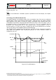
However, if no_mot_sel =’1’, register int_slo_no_mot_dur defines the time no slope data point of
any of the selected axis must exceed the threshold value int_slo_no_mot_th for an interrupt to
be asserted. The tick times of 1.28s, 5.12s and 10.24s depend on the value programmed into
int_slo_no_mot_dur<5:0>. By means of using variable tick times, a no-motion delay between 1s
and 430s may be adjusted with a register with a width of six bits.
2.6.9.2 Register slo_no_mot_th
The int_slo_no_mot_th register defines the threshold against which the calculated slope values
of each axis are compared. The scaling is independent on the selected interrupt mode. The
user must scale the int_slo_no_mot_th value according to the adjusted range.
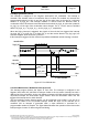
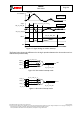
2.6.10 Data Ready Detection (Accel, Gyro and external sensors)
This interrupt fires whenever a new data sample from accel and gyro is complete. This allows a
low latency data readout.
The data update detection monitors the data_update signals for all axes and sensors. It
generates an interrupt as soon as the values for all axes and sensors which are required for the
configured output data rates have been updated.
The interrupt is cleared automatically when the update for the next sample starts or the data is
read out from the data register.
2.6.11 PMU Trigger (Gyro)
Whenever a PMU (power management unit) trigger (either wakeup or sleep) is issued,
wakeup_int in Register (0x6C) PMU_TRIGGER configures if an interrupt is send to the
application processor. If the AP wants to trigger sleeps itself for the gyro, the
gyr_wakeup_trigger is configured accordingly and no wakeup triggers are issued.
The PMU trigger interrupt is from the system perspective used in a similar manner as the
anymotion and nomotion interrupts. The PMU trigger interrupt follows the Register (0x54)
INT_LATCH configuration for resetting the interrupt.
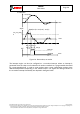
2.6.12 FIFO Interrupts (Accel, Gyro, and external sensors)
The FIFO supports two interrupts, a FIFO full interrupt and a watermark interrupt. The FIFO full
interrupt is issued when the FIFO is full and the next full data sample would cause a FIFO
overflow, which may lead to samples being deleted. Technically, that means that a FIFO full
interrupt is issued, whenever less space than two maximum size frames is left in the FIFO. The
FIFO watermark interrupt is fired, when the FIFO fill level in fifo_byte_counter in Register (0x22-
0x23) FIFO_LENGTH is above a pre-configured watermark, defined in fifo_watermark in
Register (0x46-0x47) FIFO_CONFIG.
Note: The unit of fifo_watermark is 4 bytes whereas the unit of fifo_byte_counter is single bytes.