
Datasheet


BMI160
Data sheet
Page 96
BST-BMI160-DS000-07 | Revision 0.8 | February 2015 Bosch Sensortec
© Bosch Sensortec GmbH reserves all rights even in the event of industrial property rights. We reserve all rights of disposal such as copying and passing on to
third parties. BOSCH and the symbol are registered trademarks of Robert Bosch GmbH, Germany.
Note: Specifications within this document are preliminary and subject to change without notice.
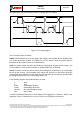
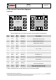
The data mode is enabled by setting the MAG_IF_1<7> = 0.
MAG_IF[2] defines the lowest address of the register data bytes to read from the MAG-
sensor and the data will be stored in the BMI160 register MAG-DATA. The data ready status
is set via drdy_mag in
Register (0x1B) STATUS, but this operation never clears drdy_mag, it is typically cleared
through reading the Register (0x04-0x17) DATA. If DRDY is not active the error bit
mag_drdy_err in Register (0x02) ERR_REG is set. MAG_IF[3] defines the register address
of the magnetometer to start a measurement in forced mode in the magnetometer register
map. Reading of the data is done in a single I2C read operation with a burst length of 8
bytes.
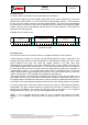
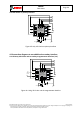
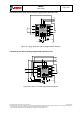
3.3.2 Camera module connected to secondary interface for OIS
BMI160 supports specific optical image stabilization (OIS) applications with a dedicated
interface. This interface is used for direct access to pre-filtered gyroscope data with minimum
latency. Pre-filtered gyroscope data is available at output data rate (ODR) of 6.4 kHz and can
be read out via OIS fast mode SPI interface at 400kHz maximum speed.
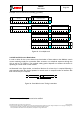
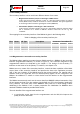
The OIS SPI interface supports 3-wire SPI as well as 4-wire SPI.
The timings of the secondary SPI interface are the same as for the primary SPI interface, see
chapter 3.2.2. The connection diagrams are depicted in chapter 4.3.