
Information


BMA250E
Data sheet
Page 17
BST-BMA250E-DS004-06 | Revision 1.3 | April 2015 Bosch Sensortec
© Bosch Sensortec GmbH reserves all rights even in the event of industrial property rights. We reserve all rights of disposal such as copying and passing on to
third parties. BOSCH and the symbol are registered trademarks of Robert Bosch GmbH, Germany.
Note: Specifications within this document are subject to change without notice.
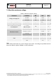
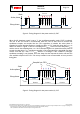
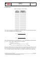
The sleep time for lower-power mode 1 and 2 is set by the (0x11) sleep_dur bits as shown in
the following table:
Table 3: Sleep phase duration settings
(0x11)
sleep_dur
Sleep Phase
Duration
t
sleep
0000b
0.5ms
0001b
0.5ms
0010b
0.5ms
0011b
0.5ms
0100b
0.5ms
0101b
0.5ms
0110b
1ms
0111b
2ms
1000b
4ms
1001b
6ms
1010b
10ms
1011b
25ms
1100b
50ms
1101b
100ms
1110b
500ms
1111b
1s
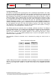
The current consumption of the BMA250E in low-power mode 1 (I
DDlp1
) and low-power mode 2
(I
DDlp2
) can be estimated with the following formulae:
activesleep
DDactiveDDsumsleep
DDlp
tt
ItIt
I
1
.
activesleep
DDactiveDDsbmsleep
DDlp
tt
ItIt
I
2
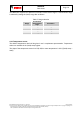
When estimating the length of the wake-up phase t
active
, the corresponding typical wake-up time,
t
w,up1
or t
w,up2
and t
ut
(given in Table 4) have to be considered:
If bandwidth is >=31.25 Hz:
t
active
= t
ut
+ t
w,up1
- 0.9 ms (or t
active
= t
ut
+ t
w,up2
- 0.9 ms)
else:
t
active
= 4 t
ut
+ t
w,up1
- 0.9 ms (or t
active
= 4 t
ut
+ t
w,up2
- 0.9 ms)
During the wake-up phase all analog modules are held powered-up, while during the sleep
phase most analog modules are powered down. Consequently, a wake-up time of at least t
w,up1
(t
w,up2
)
is needed to settle the analog modules so that reliable acceleration data are generated.