
Information

BMA250E
Data sheet
Page 28
BST-BMA250E-DS004-06 | Revision 1.3 | April 2015 Bosch Sensortec
© Bosch Sensortec GmbH reserves all rights even in the event of industrial property rights. We reserve all rights of disposal such as copying and passing on to
third parties. BOSCH and the symbol are registered trademarks of Robert Bosch GmbH, Germany.
Note: Specifications within this document are subject to change without notice.
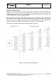
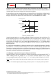
4.7.3 Electrical behaviour (INT pin# to open-drive or push-pull)
Both interrupt pins can be configured to show the desired electrical behaviour. The ´active´ level
of each interrupt pin is determined by the (0x20) int1_lvl and (0x20) int2_lvl bits.
If (0x20) int1_lvl = ´1´ (´0´) / (0x20) int2_lvl = ´1´ (´0´), then pin “INT1” / pin “INT2” is active ´1´
(´0´). The characteristic of the output driver of the interrupt pins may be configured with bits
(0x20) int1_od and (0x20) int2_od. By setting bits (0x20) int1_od / (0x20) int2_od to ´1´, the
output driver shows open-drive characteristic, by setting the configuration bits to ´0´, the output
driver shows push-pull characteristic. When open-drive characteristic is selected in the design,
external pull-up or pull-down resistor should be applied according the int_lvl configuration.
4.7.4 New data interrupt
This interrupt serves for synchronous reading of acceleration data. It is generated after storing a
new value of z-axis acceleration data in the data register. The interrupt is cleared automatically
when the next data acquisition cycle starts. The interrupt status is ´0´ for at least 50µs.
The interrupt mode of the new data interrupt is fixed to non-latched.
It is enabled (disabled) by writing ´1´ (´0´) to bit (0x17) data_en. The interrupt status is stored in
bit (0x0A) data_int.
Due to the settling time of the filter, the first interrupt after wake-up from suspend or standby
mode will take longer than the update time.