
Information

BMA250E
Data sheet
Page 33
BST-BMA250E-DS004-06 | Revision 1.3 | April 2015 Bosch Sensortec
© Bosch Sensortec GmbH reserves all rights even in the event of industrial property rights. We reserve all rights of disposal such as copying and passing on to
third parties. BOSCH and the symbol are registered trademarks of Robert Bosch GmbH, Germany.
Note: Specifications within this document are subject to change without notice.
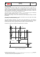
4.7.6.4 Axis and sign information of tap sensing
The sign of the slope of the first tap which triggered the interrupt is stored in bit (0x0B) tap_sign
(´0´ means positive sign, ´1´ means negative sign). The value of this bit persists after clearing
the interrupt.
The axis which triggered the interrupt is indicated by bits (0x0B) tap_first_x, (0x0B) tap_first_y,
and (0x0B) tap_first_z.
The bit corresponding to the triggering axis contains a ´1´ while the other bits hold a ´0´. These
bits are cleared together with clearing the interrupt status.
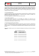
4.7.6.5 Tap sensing in low power mode
In low-power mode, a limited number of samples is processed after wake-up to decide whether
an interrupt condition is fulfilled. The number of samples is selected by bits (0x2B) tap_samp
according to Table 12.
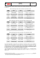
Table 12: Meaning of (0x2B) tap_samp
(0x2B)
tap_samp
Number of Samples
00b
2
01b
4
10b
8
11b
16